EN



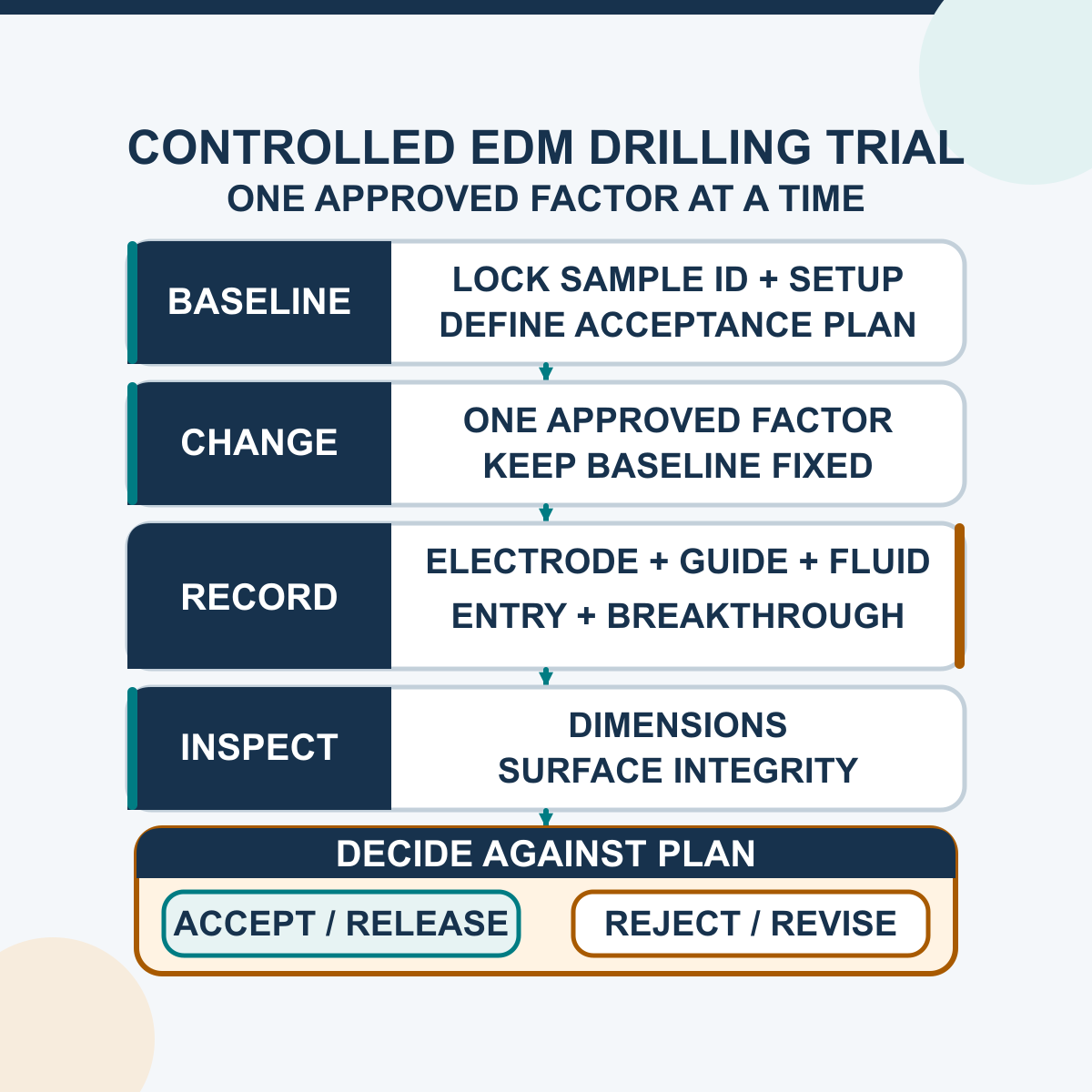
Optimizing EDM drilling means improving a defined result under controlled conditions—not applying one universal set of current, pulse, feed, rotation or flushing values. Start with a stable baseline, change one approved factor at a time, drill representative samples and measure every characteristic that matters to the drawing. A shorter drilling time is useful only when diameter, position, form, entry/exit condition and any required surface-integrity limits still pass.
EDM hole drilling commonly uses a rotating tubular electrode and process fluid to support discharge-gap recovery, cooling and removal of eroded material. The result depends on the complete system: machine and generator, workpiece, electrode, guide, fluid path, fixture, datum, hole geometry, settings, environment and inspection method. Record that system before attempting to improve it.
Define the Result Before Changing a Parameter
Write the acceptance plan first. Identify the exact material and heat-treatment condition, finished-hole diameter, depth, through/blind requirement, entry angle, datum and position, quantity and production timing boundary. If roundness, taper, straightness, surface texture, recast layer, heat-affected material or microcracks matter, state the required characteristic and inspection method rather than hiding them inside the word “precision.”
| Result to define | What the plan should state | Typical evidence route |
|---|---|---|
| Diameter | Size specification, measurement location and inlet/outlet treatment | Calibrated optical, contact or section-based method suitable for the hole and tolerance |
| Position and orientation | Datum system, basic coordinates, position/orientation rule and sampling | Measurement referenced to the released datum, not only the machine display |
| Form through depth | Roundness/cylindricity, straightness or taper requirement where applicable | Multiple-depth measurement or an agreed representative section |
| Entry and exit | Allowed flare, edge damage, breakthrough condition and inspection side | Documented inlet/outlet images and dimensional checks |
| Surface integrity | Surface texture and any recast, heat-affected or crack acceptance rule | Specified texture test and, when required, a prepared cross-section or other approved method |
| Time | Start/end event and whether setup, electrode handling, breakthrough and inspection are included | Timestamped trial record using the same boundary for every comparison |
The measuring method must be capable of resolving the specified characteristic, and the acceptance rule should account for the agreed sampling and measurement uncertainty. Do not convert a machine command increment into proof of finished-hole accuracy.
Establish a Repeatable Baseline
Use a representative workpiece or coupon with the same material grade, heat treatment, thickness, entry surface and hole orientation as the intended job. Fix the machine, generator program/revision, electrode and guide, working fluid and filtration condition, fixture/datum, environment and inspection plan. Label every sample and retain the baseline result before changing anything.
A useful baseline record includes:
- machine model/serial and the control or generator program actually used;
- workpiece material, grade, condition, dimensions, lot and electrical contact;
- electrode material/construction, outside and inside diameter, lot and usable length;
- guide identity/condition, rotation condition and any checked runout/alignment value;
- approved working fluid, visible condition, filtration state, delivery path and machine-displayed setting;
- fixture, datum, entry surface, hole depth/angle and through/blind definition;
- all electrical, feed/servo, rotation and fluid settings exactly as shown on the machine;
- timing boundary, measured results, inspection equipment and operator/inspector.
Repeat enough baseline holes to show whether the process is stable for the intended decision. One unusually good hole is not a process window, and one unusually bad hole should trigger a setup review before the parameter is blamed.
Change One Approved Factor at a Time
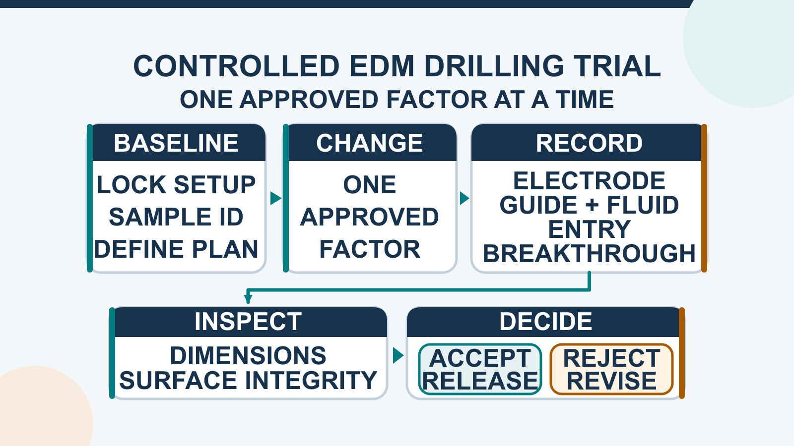
Choose one response to improve—for example, elapsed drilling time, outlet taper or electrode consumption—while keeping the remaining acceptance limits fixed. Change one parameter within the machine supplier's approved operating range, reproduce the same sample pattern and compare the same measurements. If several factors are changed together, the cause of an improvement or failure cannot be separated.
- Lock the baseline and define the trial question.
- Select one approved factor and a controlled change level.
- Assign sample IDs before drilling.
- Observe stability, alarms, fluid return, electrode condition, entry and breakthrough.
- Measure the same characteristics with the same method.
- Accept, reject or repeat the change against the written rule.
- Freeze the approved revision before production and retain the record.
Electrical energy, pulse timing, gap/servo response, Z feed, electrode rotation and fluid delivery can interact. Their names and permitted values vary by generator and control. Use the actual machine documentation and do not translate a parameter number from another brand or model as though it were equivalent.
Control Flushing, Debris and the Fluid Path
A stable discharge needs a repeatable fluid and debris-removal condition. Before changing an electrical setting, check that the approved fluid is at the required level and condition, the electrode bore and delivery path are clear, filters and return paths are serviceable, connections do not leak and debris is not accumulating around the entry. Record the machine-displayed value rather than describing the setup only as “high pressure.”
Do not assume that progressively increasing pressure will fix every deep-hole problem. Excessive or unstable delivery can create leakage, spray/mist, electrode deflection or another source of variation. If flow is blocked, a hose/seal is damaged, pressure behaves abnormally or the enclosure/guarding cannot contain the process, stop the trial and inspect the system safely under the machine manual.
Track Electrode, Guide, Rotation and Wear
The electrode is consumed during EDM drilling. Its outside and inside diameter, material/construction, straightness/concentricity, unsupported length and wear influence both the fluid path and measured hole. Guide wear, contamination, misalignment or lateral play can add runout or drift. Rotation should be checked for smooth operation and visible eccentricity before a parameter trial is interpreted.
Measure or otherwise record electrode consumption under the agreed method, and establish a replacement rule linked to the accepted result. Do not infer that the smallest available electrode is automatically fastest or that a nominal electrode diameter equals the finished hole. The current English D703 and DD703 pages list φ0.3–φ3.0 mm as an electrode-diameter field; spark-gap overcut, wear, runout, guide condition, depth, flushing and entry/breakthrough conditions still affect the measured hole.
Treat Entry, Full Depth and Breakthrough as Separate Stages
The process condition can change as the electrode first enters the surface, advances through the hole and breaks through the far side. Observe each stage. Inspect inlet and outlet separately, measure form through depth where required, and record whether the fluid return or discharge behaviour changes. A flat test coupon may not reproduce a curved, coated, angled or interrupted production surface.
For a blind feature, define the depth/endpoint and inspection method before the trial. For a through hole, define how breakthrough is detected and whether elapsed time ends at first breakthrough or after a finishing/flush stage. Never assume “burr-free” or undamaged entry/exit without inspection.
Balance Drilling Time With Dimensional and Surface Acceptance
Increasing discharge energy may raise material removal in a particular setup, but it can also alter electrode wear, overcut, taper, entry/exit condition and thermal surface effects. Optimization therefore needs a response table rather than a “maximum energy equals maximum productivity” rule. Review the fastest trial that passes every required characteristic, not the fastest individual hole.
EDM is a thermal process. Where part function makes surface integrity important, include the specified surface-texture method and a representative inspection for recast/white layer, heat-affected material or microcracking. A visual check or average roughness value alone may not address the released engineering requirement.
| Trial observation | First checks before another setting change | Evidence needed for a decision |
|---|---|---|
| Unstable discharge, repeated shorting or interrupted feed | Electrical contact, debris path, fluid delivery, electrode bore, guide and approved gap/servo state | Alarm/event log, sample ID and post-trial electrode/guide observation |
| Large inlet-to-outlet difference | Wear, runout/alignment, depth, debris evacuation, entry and breakthrough behaviour | Inlet/outlet and, if required, multiple-depth or section measurements |
| Position drift across a pattern | Datum, fixture, workpiece movement, thermal/environmental change and positioning method | Measured positions to the released datum and drilling order/time record |
| Faster time but failed hole quality | Which changed factor altered wear, overcut, form, entry/exit or surface integrity | Complete comparison against every acceptance characteristic |
| Result changes after electrode replacement | Electrode lot/construction, guide fit, setup length, alignment and baseline restoration | Before/after sample set under the same approved process revision |
Use the Correct Control Model for the Job
The D703 is a non-CNC, single-axis EDM hole-drilling machine; “single-axis” refers to the controlled/servo Z-axis feed. Workpiece location and the setup method must therefore be defined rather than described as programmed multi-axis positioning. The DD703 is the CNC/multi-axis option when programmed coordinate positioning or repeated patterns are required. CNC coordinates still do not prove finished-hole position: the datum, fixture, machine condition, process and measurement remain part of acceptance.
Start at the EDM drilling machine range, then compare D703 and DD703 by control need, physical capacity and the representative trial—not from a generic speed/precision claim.
Apply Stop and Safety Boundaries
Follow the supplied machine, generator, electrode, working-fluid and site-safety instructions. Keep required guards and interlocks in service. Stop the process before changing an electrode/guide or clearing a fluid path, and depressurize the relevant circuit before opening it. Electrical cabinets, generators, high-voltage components, interlocks and internal pressure-system service belong to qualified personnel under the applicable isolation/lockout procedure.
Stop the trial and escalate under the site procedure if any of the following occurs:
- persistent arcing/shorting, repeated alarms or uncontrolled feed behaviour;
- abnormal vibration, electrode runout, guide damage or unexpected electrode bending;
- blocked delivery, pressure instability, leakage, damaged hose/seal or uncontrolled spray/mist;
- overheating, smoke, unusual odour, damaged cable/connection or an electrical/interlock fault;
- fixture/workpiece movement, loss of datum or an inspection result outside the stop limit.
Do not bypass an interlock or open energized equipment to continue a parameter experiment. Local legal requirements and the installed-machine manual take precedence over this general guide.
Build the Sample and RFQ Record
For a new application, send the drawing and the representative worst-case feature rather than asking for “the fastest settings.” A useful technical review contains:
- exact workpiece material/grade, heat treatment, dimensions and weight;
- finished-hole diameter, depth, quantity, entry angle and through/blind requirement;
- datum, position, roundness/form, taper/straightness and entry/exit acceptance;
- surface-texture and metallurgical surface-integrity requirements;
- inspection method, sampling plan and any destructive-section allowance;
- cycle-time definition, production quantity and shift pattern;
- available machine/control preference, electrode constraints, flushing/fixture access and automation requests;
- destination country, available voltage/frequency and applicable acceptance documentation.
The approved sample record should connect every part ID to the machine/setup revision, parameter revision, electrode/guide/fluid condition, timing and measured result. If production material, geometry, electrode, guide, fluid system, software/parameter revision, fixture or acceptance method changes, define whether revalidation is required.
Frequently Asked Questions
Does higher discharge energy always drill faster?
No universal answer applies. A change may alter material removal, electrode wear, discharge stability, overcut, taper, entry/exit condition and thermal surface effects. Test one approved change under a fixed baseline and accept it only when the complete result passes.
Should flushing pressure always increase with hole depth?
No. Use the machine's approved fluid-delivery range and verify the whole path, including the electrode bore, filters, seals, enclosure and return flow. Blockage, leakage or unstable pressure requires a safe inspection, not an uncontrolled increase.
Is electrode diameter the same as finished-hole diameter?
No. D703 and DD703 currently list φ0.3–φ3.0 mm as an electrode-diameter range. Finished size also depends on the discharge gap, electrode wear/runout, guide, material, depth, flushing, entry/breakthrough and process settings. State and measure the required finished hole separately.
Can a successful parameter set be copied to another part?
It may be a starting reference only when the machine, material, electrode, guide, fluid path, geometry, fixture and acceptance method remain comparable. Re-establish the baseline and revalidate any change that can affect the result.
How should drilling speed be reported?
Define the start/end events and whether the figure includes setup, approach, drilling, breakthrough, electrode/guide handling, inspection and rejected parts. Use the same boundary and sample conditions for every comparison.
Request a Controlled EDM Drilling Review
Compare the current D703 non-CNC single-axis machine and DD703 CNC/multi-axis machine, then send the drawing, material, representative hole and acceptance plan. HarsMarg can review machine fit, open configuration questions and the sample evidence required before a technical quotation or process revision is accepted.
Table of Contents
- Define the Result Before Changing a Parameter
- Establish a Repeatable Baseline
- Change One Approved Factor at a Time
- Control Flushing, Debris and the Fluid Path
- Track Electrode, Guide, Rotation and Wear
- Treat Entry, Full Depth and Breakthrough as Separate Stages
- Balance Drilling Time With Dimensional and Surface Acceptance
- Use the Correct Control Model for the Job
- Apply Stop and Safety Boundaries
- Build the Sample and RFQ Record
- Frequently Asked Questions
- Request a Controlled EDM Drilling Review