EN




EDM can be useful for features that are difficult to produce by direct mechanical cutting, but quality must be demonstrated on the finished part. Assess dimensions, surface roughness and any specified surface-integrity requirements separately. A machine specification or a visually smooth surface is not, by itself, evidence that every drawing requirement has been met.
Before machining, agree which features will be inspected, how they relate to the drawing datums, and what records will support acceptance. This connects the process to a measurable result rather than a general claim of superior precision. The following checks apply to proposed trials as well as completed parts; they are not a universal test standard or a performance guarantee.
EDM Mechanisms and Part Inspection
Noncontact Erosion and Dimensional Verification
Conventional EDM removes material from a conductive workpiece through electrical discharges across a gap in a dielectric medium. Noncontact erosion does not mean that the finished part is free from thermal effects, dimensional change or surface alteration. The drawing and inspection results, not the absence of a cutting edge, determine acceptance.
Record the machine and configuration, workholding, datum references and machining sequence used for the inspected part. Distinguish axis positioning or repeatability data from actual feature measurements. A profile, cavity or hole must be evaluated in its own geometry and material condition.
Include the dielectric and flushing arrangements in the process record where relevant to the job. They are supporting information for reproducing machining conditions, not substitutes for a dimensional report. If a setup changes, identify the change when comparing results.
Process Stages and Surface Requirements
Identify the roughing and finishing stages used for the part. Pulse conditions and the machining sequence influence the resulting surface, but a parameter setting is not a measured roughness value. Report the process stage at which inspection took place.
Keep the required roughness parameter and units distinct from requirements concerning cracks, recast material or other surface changes. A result that meets a roughness limit does not alone establish compliance with a separate surface-integrity requirement.
If grinding, polishing or another operation follows EDM, state whether the inspection result describes the EDM surface or the final surface after that operation. This avoids comparing results taken at different production stages.
Dimensional Acceptance for Wire EDM Parts
Define the Profile and Measurement Locations
Wire EDM uses a wire electrode to produce a programmed cut. Specify the actual wire and wire-handling arrangement used rather than assuming that every machine feeds the same consumable in the same way. For inspection, identify the profile, datum references, corner requirements and relevant locations through the workpiece thickness.
When reviewing an EDM machining proposal, supply the drawing limits and ask which finished-part measurements will demonstrate them. Record the inspected feature and its location. Do not substitute a machine positioning claim for evidence about that particular profile.
Where taper cutting, wire threading or other control functions matter to the job, confirm that they are installed and record whether they were used. Their presence does not independently prove the dimensions or surface quality of the resulting part.
Record Wire EDM Surface Results
A roughness report should identify the required parameter, units, surface location, measurement direction and applicable instrument settings. Agree the method appropriate to the specified surface, including relevant filtering and evaluation length. Do not treat an isolated Ra value as comparable to a result obtained under unspecified conditions.
Recast material is material that has resolidified on the machined surface. Its assessment is separate from ordinary profile roughness measurement. Where the customer specifies a recast, crack or other surface-integrity limit, agree the examination method and reporting requirements before accepting the part.
For demanding components, identify which surfaces and features require these additional checks. Neither a fine finish nor a particular generator or finishing strategy removes the need to demonstrate the requirements specified for the job.
Dimensional Acceptance for Sinker EDM Cavities
Separate Electrode Data from Cavity Measurements
Sinker EDM uses a shaped electrode to form a cavity. The electrode geometry is useful process information, but it is not the finished cavity measurement. Define the cavity features, depth references and measurement access needed for acceptance.
When comparing EDM machining equipment for a cavity, record the electrode, gap-related allowance, flushing arrangement and any installed motion strategy used for the proposed job. Confirm relevant features on the actual machine rather than assuming that orbital motion or compensation is universal.
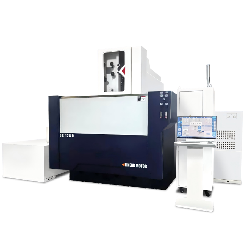
Report electrode inspection, machine positioning information and finished cavity inspection as separate records. Evaluate the cavity against the drawing, including the locations and geometric requirements agreed for measurement. Neither an accurate electrode nor positioning repeatability alone establishes cavity conformance.
Record Material Condition at Final Inspection
Identify the actual material grade and heat-treatment condition of the workpiece. EDM can be considered for conductive hard materials, but eligibility and processing conditions still require material-specific review. Hardness alone does not establish the expected dimensional or surface result.
Record the production sequence, including heat treatment and any operations following EDM. State the condition of the part at final inspection. A measurement from an earlier stage should not be presented as acceptance of a later, altered condition without the necessary checks.
Compare alternative processes against the same drawing and final acceptance requirements. There is no need to assume that mechanical machining must finish every part in a soft state, or that EDM is always the only route to an acceptable hardened component.
Evidence of Consistency Across a Production Batch
Traceable Programs and Inspection Records
Keep the program revision, relevant process settings, machine configuration and inspected part identity together. These records help explain what produced a result and what changed between jobs. They do not replace inspection of the features being accepted.
Treat stored parameters as starting conditions for the specified setup, not a promise that every subsequent part will match the first. Record changes in material, geometry, tooling, setup or other relevant conditions, and apply the agreed checks when those changes affect the job.
If process capability is requested, define the characteristic, specification limits, production data and suitable analysis method. A single conforming part does not establish Cpk or demonstrate a stable production process. Report any capability statement with its data scope and assumptions.
Inspection Around Interruptions and Automated Runs
For any approved automated operation, agree what checks are needed after an interruption or restart. Record relevant events such as wire breaks, electrode changes or setup adjustments. Confirm operating and safety arrangements on the actual machine; noncontact erosion is not permission for unattended running.
Assess consistency using measurements from the agreed production sample. Identify which parts were inspected and whether their material, setup and process conditions differed. Do not describe a sampled result as proof that every unmeasured part is identical.
Where a machine provides process feedback or dimensional measurement, identify the installed function and the records it produces. Distinguish control information used during machining from the evidence required for final part acceptance.
Match the Acceptance Plan to the Part
Tooling Features and Surface Requirements
For tooling, connect each reported measurement to the specified cavity, profile, edge or datum feature. A useful report explains which drawing requirement each result addresses. General claims about EDM being the preferred tooling process cannot make that connection.
For a mold cavity, identify the surfaces subject to roughness requirements and report their condition after the agreed final operation. Any claim about molding performance or cycle time needs separate application evidence; it should not be inferred from roughness alone.
For a die profile, inspect the specified edges, radii and surface condition. Do not assume that an EDM-cut edge is automatically burr-free, meets every corner requirement or extends tool life. Acceptance concerns the measured and examined part, not the process label.
Customer Requirements for Critical Features
For a hole or another critical feature, agree the dimensions, locations and surface evidence required by the customer before machining. Make any inaccessible measurement area or need for a representative specimen explicit when planning the inspection.
Where surface integrity is specified, use the material and drawing requirements to agree the examination scope. A visual check or a roughness result may answer a different question from an examination for subsurface or metallurgical changes.
For regulated or sensitive components, the customer's specifications and applicable qualification procedures determine the evidence required. EDM is not, by itself, proof of medical, aerospace or other regulatory acceptance. Send the drawing, material condition, inspection requirements and intended machine configuration when requesting a technical proposal.
FAQ
What Material Information Belongs in an EDM Inspection Report
Record the actual material grade and its condition during machining and final inspection, including relevant heat treatment or later operations. If the proposed material has not been qualified for the process, resolve that question separately instead of assuming that electrical conductivity alone establishes an acceptable result.
Does Positioning Accuracy Prove Finished Part Accuracy
No. Positioning data describe a machine test under its stated conditions. Finished-part acceptance requires measurements of the specified features against the drawing and datums, using a suitable method. Include relevant measurement uncertainty when interpreting results near an acceptance limit.
How Do Prototype and Production Records Differ
A prototype report describes the inspected specimen and conditions. A production report should also define the inspected sample, relevant changes and the scope of any consistency claim. A successful trial is useful evidence, but it does not automatically establish batch capability.
How Should EDM Surface Roughness Be Reported
State the parameter and units, surface location, measurement direction, applicable measurement settings and production stage. Identify the instrument and method, with calibration and uncertainty information appropriate to the acceptance decision. Keep roughness results separate from any additional surface-integrity examination and do not replace measured results with a generic EDM finish range.