EN
EN



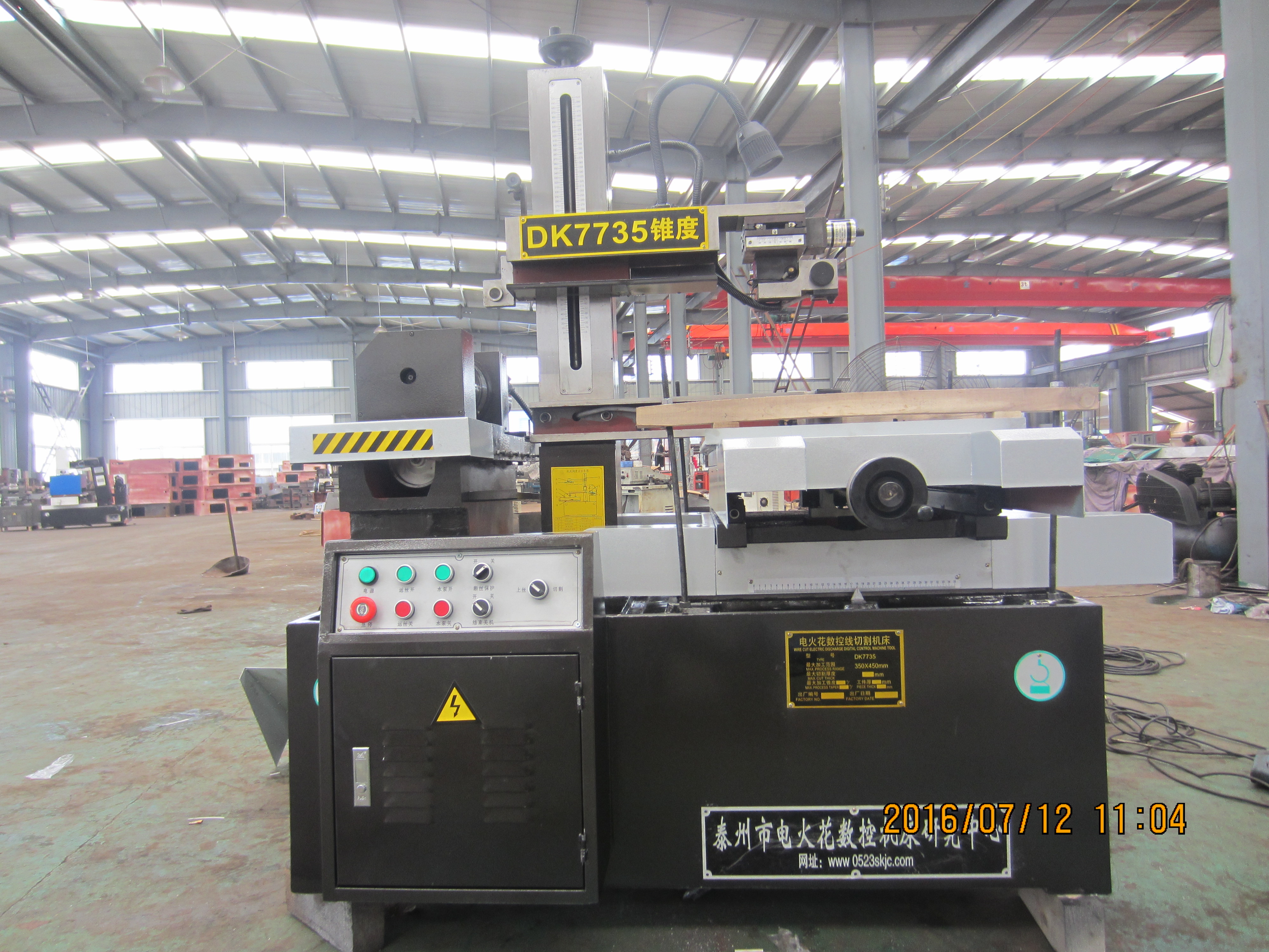
For HarsMarg single-cut and multi-cut Wire EDM machines, extending wire life means keeping the reusable molybdenum wire and its complete reciprocating transport system in a stable, serviceable condition. Inspect the wire, drum winding, reversal, tension, guides or guide wheels, electrical contact blocks, approved working fluid, flushing and qualified cutting conditions. Replace the wire when the supplied manual or documented condition evidence requires it—not after a universal number of hours.
This is different from a one-way Wire EDM machine that continuously feeds new brass or coated wire from a spool and discards it after the cutting zone. HarsMarg's current single-cut and multi-cut families in scope use molybdenum wire stored on a wire drum and moving back and forth through the gap. Advice about fresh-wire feed rate, spool consumption, wire choppers or discard cost must not be copied into this maintenance plan.
What Does “Wire Life” Mean on a Reciprocating Wire EDM?
The loaded molybdenum wire is reused, but it is not wear-free. Repeated discharges can erode its surface and change its local cross-section, while travel through the drum, tensioning and guide system adds mechanical handling. Published experimental work on used molybdenum wire has observed surface craters, globules and microholes after machining. The practical objective is therefore to keep wire condition and transport stable enough to meet the qualified cutting result without running the wire until it fails.
| System Question | HarsMarg Reciprocating System in Scope | One-Way Consumable-Wire Guidance Not to Transfer |
|---|---|---|
| Electrode wire | Reusable molybdenum wire approved for the model and job | Brass, coated brass or steel-core wire assumed to be universal |
| Wire movement | Wire travels forward and reverse and is rewound on the wire drum | Fresh wire continuously leaves a supply spool and is discarded after one pass |
| Main maintenance focus | Wire condition, orderly winding, anchoring, reversal, tension, wire path, contacts, fluid and cutting stability | Spool feed rate, discard mechanism, wire chopper and pounds or length consumed per hour |
| Replacement decision | Manual limits plus documented wire/process condition and accepted workpiece result | A generic spool-change interval or wire-consumption target |
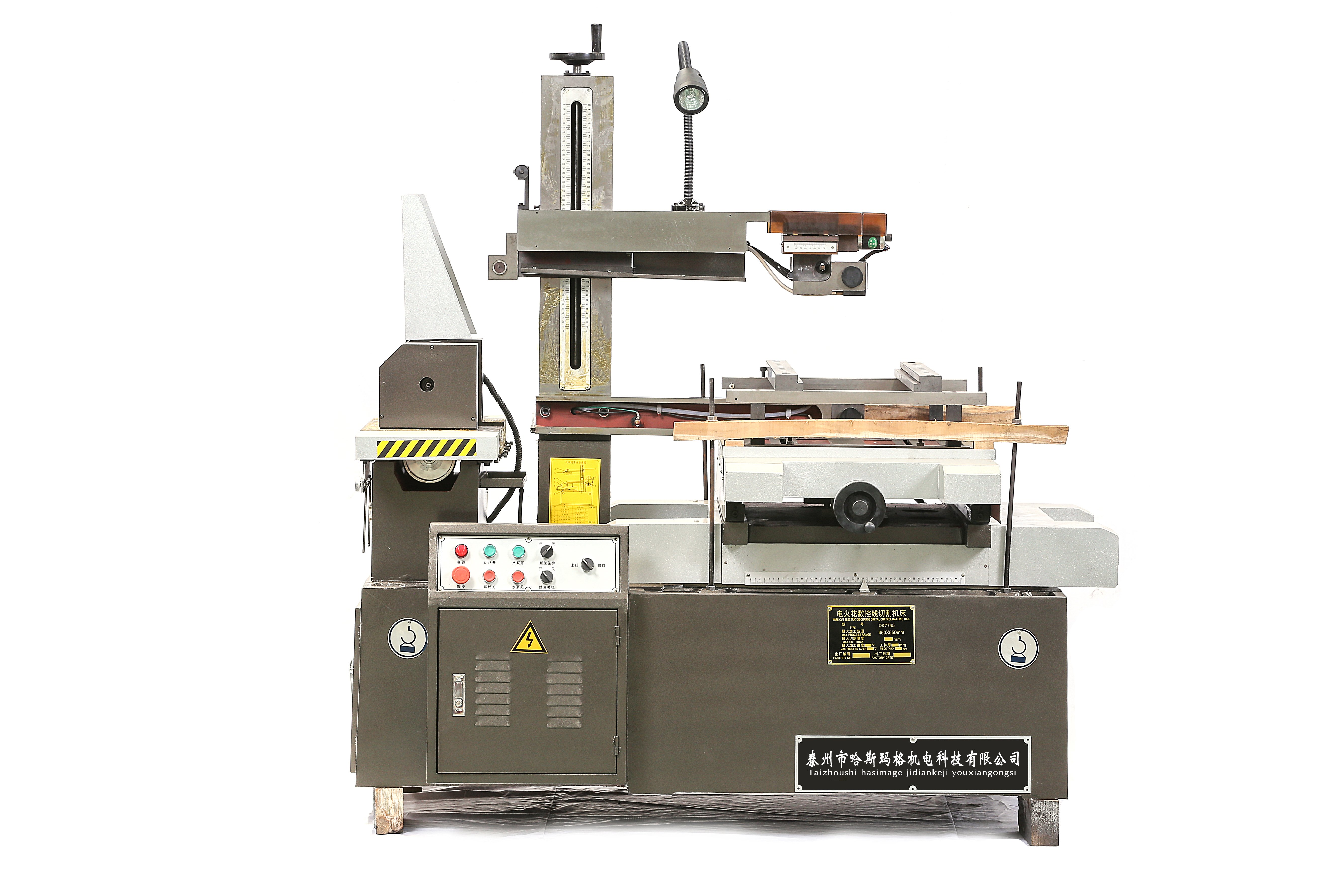
The image file was previously labelled as DK7735, but the visible machine nameplate identifies it as DK7745. The corrected description above prevents the image from being mistaken for another model.
Establish a Safe, Repeatable Baseline
- Use the exact model manual. Confirm the approved wire material, diameter, loading/winding method, tension procedure, working fluid and operator checks. Do not transfer a limit from a different Wire EDM architecture.
- Make the machine safe. Stop the cycle and follow the supplied manual and site isolation procedure before touching the drum, wire path, guides, contact components or a trapped workpiece. Guards and interlocks must not be bypassed.
- Preserve the last accepted setup. Record the program, offset, electrical condition, wire specification, tension setting or method, wire speed, fluid condition, flushing arrangement, fixture and inspection result before changing anything.
- Describe the symptom. Note whether the issue is repeated wire breakage, unstable cutting, short circuits, winding/reversal problems, slower cutting, roughness or dimensional drift, and where in the path or program it occurs.
- Change one controlled variable. Simultaneous tension, power, speed and fluid changes hide the cause and make the result difficult to reproduce.
For the complete setup sequence, use the Wire EDM machine setup checklist together with the selected model manual.
Inspect the Molybdenum Wire and Drum Winding
Inspect the accessible wire before starting and whenever cutting behaviour changes. Look for kinks, flattening, obvious surface damage, contamination, local thinning or diameter irregularity, and damage caused by poor handling or contact with a worn component. Do not use colour alone as a replacement rule, and do not assume that a visually clean wire has unlimited remaining life.
On the wire drum, check the conditions allowed by the manual:
- orderly winding without crossed layers, loose loops, bunching or a local pile-up;
- secure anchoring and sufficient usable wire for the planned job;
- correct travel limits and clean reversal without impact, hesitation or wire release;
- no contact between the wire and an unintended machine edge, guard or contaminated surface;
- consistent tracking in both directions where the manual permits an operational observation.
Never improvise a splice, straighten a damaged loaded section or rewind the drum while the machine can move. Use the approved loading and replacement procedure. If wire damage repeats at the same drum position or at reversal, stop and inspect the winding, travel limits and related drive/tension components before fitting another wire.
Set Tension for the Model and Job—Not as High as Possible
Wire tension helps limit bow and vibration, but more tension is not automatically better. Insufficient tension can allow unstable tracking or geometric error; excessive tension adds mechanical load to a wire already weakened by discharge erosion and can increase break risk. Use the approved setting or procedure for the wire diameter, machine, workpiece thickness, material, cut strategy and required result.
A reciprocating system also has to remain stable through direction changes. Observe whether the symptom appears only in one travel direction, near reversal or at the same feature in the program. Do not describe the tensioner as a closed-loop monitoring or correction system unless that function is confirmed for the exact controller and supplied configuration.
Maintain the Wire Path, Guides and Electrical Contacts
The actual wire path varies by model, but it may include guide wheels or guide components, an alignment device, tension components, electrical contact blocks and the drum. Dirt, grooves, looseness, misalignment, seized rotation or a damaged contact face can scrape, heat or deflect the wire and can make a new wire fail in the same way as the old one.
- clean only the components and surfaces identified in the supplied maintenance procedure;
- inspect the fitted guide/roller path for debris, grooves, damage, free movement and secure mounting;
- inspect accessible electrical contact blocks for contamination, uneven wear, pitting or abnormal heat evidence under the manual's procedure;
- confirm the wire follows the intended path and vertical alignment before cutting;
- replace a wear component at the model/manual limit rather than polishing, bending or modifying it to hide the symptom.
Generator cabinets, protected parameters, electrical connections, drive systems, safety interlocks and formal calibration require authorised, qualified service personnel under the site's energy-isolation rules.
Control the Working Fluid, Filtration and Flushing
Working fluid supports insulation, cooling and debris removal in the cutting zone. Contamination, blocked circulation or poor nozzle direction can concentrate abnormal discharges and heat at the wire. Use only the fluid approved for the exact model and follow the machine/fluid instructions for preparation, level, service condition and disposal.
- check level, visible contamination, filter condition, circulation, leakage and return flow;
- confirm that the intended nozzles or outlets reach the cutting zone and are not blocked or displaced;
- remove debris from the gap without using uncontrolled flow that moves a thin workpiece or destabilises the wire;
- measure concentration, conductivity or temperature only where the supplied manual or fluid instruction specifies the method and acceptable range;
- do not import deionisation-resin settings, automatic-conductivity functions or fluid intervals from a one-way brass-wire machine.
Use Qualified Cutting Parameters
Discharge energy, pulse timing, wire speed, tension, feed demand, workpiece thickness/material, flushing and wire condition interact. A setting that is too aggressive for the actual gap can increase erosion and break risk; a poorly matched low-energy condition can also become unstable. Start with the exact controller/model guidance and a qualified condition for the material, thickness, wire and cut stage.
Multi-cut machining should be selected for the required dimensions and surface, not advertised as a way to extend wire life. Roughing and trimming send the reusable wire through additional cycles, so record the complete cut sequence and verify wire/process condition. When cycle time is the concern, compare the whole accepted process using the Wire EDM cutting-speed guide rather than increasing power until the wire breaks.
Diagnose Wire Breakage and Unstable Cutting
A wire break is a symptom, not proof that the wire material is defective. Record the break location on the wire path and in the program, the travel direction, whether it occurs near reversal, and the machine state immediately before the event.
| Observed Symptom | Check First | Verification Boundary |
|---|---|---|
| Break repeats at the same physical point in the wire path | Kink or local thinning, drum winding, guide/roller groove, contact-block damage, unintended rubbing and alignment | Make the machine safe, inspect the corresponding wire/component and correct the confirmed cause before reloading |
| Break occurs near direction reversal | Winding, anchoring, travel limits, tension behaviour and reversal/drive condition | Use the manual's reversal check; drive or protected adjustment belongs to qualified service |
| Break repeats at the same workpiece feature | Debris trapping, flushing access, thickness/geometry change, workpiece contact, fixture movement and programmed condition | Reproduce on representative material with the last accepted setup and change one verified variable |
| Short circuits or cutting instability increase gradually | Wire condition, fluid/filter/circulation, debris, contacts, guides, workpiece electrical contact and parameter revision | Compare alarms, interruptions and cycle observations with a documented accepted reference |
| Surface or dimensions drift without a break | Wire/tension/path plus offset, guide alignment, fixture/datum, thermal state, fluid/debris and inspection method | Inspect a reference part using the same locations and method; do not blame wire wear from one result alone |
| Contact area shows abnormal heat, pitting or arcing evidence | Wire contact, contamination, contact-block wear/position and electrical connection under the approved procedure | Stop the machine; electrical or protected-component work requires authorised service |
When Should Reusable Molybdenum Wire Be Replaced?
There is no reliable universal hour, shift or job-count interval. Follow the selected model's manual first. Replace the wire when a specified limit is reached, when inspection finds unacceptable damage or local reduction, when a traceable wire condition remains the cause of repeated failure, or when the qualified process result cannot be maintained after other causes have been checked.
Do not wait for catastrophic breakage as the routine endpoint, and do not claim that every rough surface or slow cut proves the wire is worn out. Record the reason for replacement and verify the machine with a controlled reference feature or first article after loading and aligning the new wire.
Build a Wire-Condition Record
A practical record should identify:
- machine model, controller, serial number and date;
- wire supplier, material, diameter/specification, lot and loading date;
- winding/loading record and the tension setting or procedure used;
- workpiece material, thickness, geometry and single-cut or multi-cut sequence;
- working fluid, filtration/flushing observations and relevant manual-specified readings;
- program/condition revision, actual cycle observations, alarms, short circuits and break locations;
- dimensions, taper/profile, surface result and the measurement method;
- maintenance performed, component replaced, wire-replacement reason and post-service verification.
Trend equivalent jobs instead of combining unlike materials, thicknesses and cut strategies. A log can identify recurring causes and avoid unnecessary replacement, but it does not create a universal service-life limit.
Frequently Asked Questions
How many hours can molybdenum wire be reused?
No fixed number applies to every machine and job. Wire life depends on the wire specification and loaded condition, material, thickness, electrical conditions, wire speed, tension, fluid/flushing, cut sequence, wire-path condition and acceptance requirement. Use the model manual and documented condition/performance trend.
Can brass or coated wire replace molybdenum wire on this machine?
Do not substitute wire material or diameter unless HarsMarg's model-specific documentation or written technical confirmation approves it. One-way brass-wire systems use a different transport and consumable strategy. A wire that physically fits is not proof that the generator, guides, contacts, tension system and working fluid are compatible.
Will increasing tension prevent wire bow and improve accuracy?
Not by itself. Adequate tension helps control deflection, but excessive tension increases mechanical load and can contribute to breakage when the wire is already eroded or damaged. Use the approved condition and check wire path, flushing, electrical settings, thickness and process strategy as a system.
Does multi-cut machining extend molybdenum-wire life?
Not as a general rule. Multi-cut machining separates roughing and finishing to improve the workpiece result, but it also creates additional travel and discharge exposure. Qualify the complete sequence and monitor the wire and result; do not promise longer wire life from the number of passes.
How should unused molybdenum wire be stored?
Keep it clean, dry, protected from dust, oil, corrosion sources, impact, bending and kinks, preferably in the supplier's packaging and under the supplier's stated environmental limits. Record material, diameter, lot and opening date so the installed wire is traceable.
What information is needed to diagnose repeated wire breaks?
Provide the machine/controller, wire specification, photographs of the wire drum and path, exact break location, travel direction, workpiece material and thickness, geometry, fluid/flushing condition, parameter/condition number, alarms, recent maintenance or changes, and whether the break repeats at the same physical or programmed location.
Request a Wire EDM Technical Review
Review the full HarsMarg Wire EDM range, including the DK7735 single-cut model shown in the cover. For model selection or wire-break troubleshooting, send your drawing, material, thickness, required tolerance/roughness, cut sequence, current wire and fluid, symptom record, destination and power supply. Submit your Wire EDM application and maintenance details.
Table of Contents
- What Does “Wire Life” Mean on a Reciprocating Wire EDM?
- Establish a Safe, Repeatable Baseline
- Inspect the Molybdenum Wire and Drum Winding
- Set Tension for the Model and Job—Not as High as Possible
- Maintain the Wire Path, Guides and Electrical Contacts
- Control the Working Fluid, Filtration and Flushing
- Use Qualified Cutting Parameters
- Diagnose Wire Breakage and Unstable Cutting
- When Should Reusable Molybdenum Wire Be Replaced?
- Build a Wire-Condition Record
-
Frequently Asked Questions
- How many hours can molybdenum wire be reused?
- Can brass or coated wire replace molybdenum wire on this machine?
- Will increasing tension prevent wire bow and improve accuracy?
- Does multi-cut machining extend molybdenum-wire life?
- How should unused molybdenum wire be stored?
- What information is needed to diagnose repeated wire breaks?
- Request a Wire EDM Technical Review