EN
EN



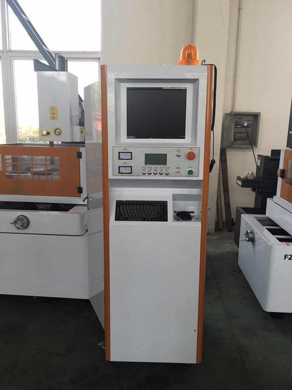
Wire electrical discharge machining can be considered for a manufacturing application when the workpiece is electrically conductive and the required cut is accessible to the wire. Start with the drawing, material condition and acceptance requirements. Compare the complete process with other suitable methods rather than assuming that a complex design makes wire EDM the fastest or least expensive choice.
For a proposed component or tool, assess how wire EDM would fit the manufacturing route. Industry labels alone do not establish suitability. The useful questions are whether the geometry can be cut on the selected machine, how the part will be held and inspected, and which additional operations are needed before acceptance.
Wire EDM Process and Configuration Review
Confirming the Cutting Process
Wire EDM uses a moving wire electrode and controlled electrical discharges across a gap to remove material from a conductive workpiece. It differs from sinker EDM, which uses a shaped electrode, and EDM hole drilling. Confirm the required feature and access before selecting a process; a capability described for one EDM process should not be assumed for another.
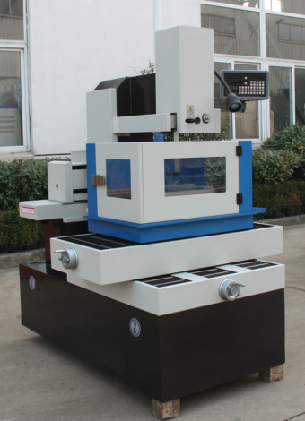
The machine's wire-running arrangement, dielectric and flushing system form part of the cutting setup. Confirm whether the proposed machine uses a continuously supplied wire or a reciprocating wire arrangement, and which wire and fluid it supports. Do not assume that a description of brass wire and deionized water applies to every wire EDM machine.
Review the generator and control functions supplied with the actual machine. Ask how the proposed setup manages the discharge gap, wire tension and changing cut conditions. Any claimed thermal or wire-deflection compensation needs to be identified and checked against the application rather than treated as a universal accuracy guarantee.
Matching Wire and Workpiece Material
Select a wire type and diameter that the machine supports. Assess the choice with the material, thickness, contour and finish requirement, not a general claim that one coating always cuts faster or straighter. A wire specification from a different machine or process is not a substitute for confirming the proposed cutting setup.
Provide the exact alloy or material grade and its condition, including relevant heat treatment. Electrical conductivity is a starting requirement, not proof that every conductive alloy, carbide or composite will achieve the same result. Check the workpiece thickness, flushing access and required finish with the selected machine and, where necessary, a representative trial cut.
A small inside radius or narrow slot must be reviewed against the wire diameter, discharge gap and programmed path. Wire size also interacts with tension, flushing and cutting conditions. Specify the smallest required feature on the drawing; do not assume that a thinner wire always gives the desired result or that a thicker wire always cuts faster.
Geometry and Dimensional Requirements
Checking Accessible Contours and Tapers
An internal contour may require an accessible starting hole and a suitable threading path. Check how the wire enters, follows the cut and exits the workpiece. A through-cut profile does not establish the ability to machine a blind cavity or an enclosed cooling channel; such features require a separate access and process review.
Evaluate Wire EDM against the requested corner details, upper and lower contours, taper and workpiece thickness. Confirm the guide movement and cutting conditions supported by the selected model. The specified geometry and surface requirements must be verified on the part rather than inferred from wire diameter or an axis count.
Do not treat additional axes as evidence that any free-form three-dimensional surface can be cut. Show the intended changes in section and confirm the wire path throughout the cut. Review whether one setup is practical, how the part and any released core will be supported, and which alignment and inspection steps remain necessary.
Defining Part Accuracy and Inspection
State dimensional tolerances separately from surface-roughness targets. A controller's command increment or display resolution does not demonstrate finished-part accuracy. Define the drawing datums, critical dimensions and measurement method, then assess whether the selected machine and cutting procedure can satisfy those requirements under the proposed conditions.
For a long cut or a temperature-sensitive part, review the workpiece condition, workshop environment and measurement conditions. Confirm any temperature-control, compensation or automatic-threading functions actually supplied. These functions do not remove the need to validate fixturing, wire conditions and the dimensions obtained on the intended workpiece.
Agree how completed parts will be measured and accepted. Cutting-condition feedback, automatic parameter adjustment and production logs are not the same as dimensional inspection. Specify the inspection stages, sampling or individual checks and response to an out-of-tolerance result; do not assume that unattended cutting establishes the conformity of every part.
Application-Specific Acceptance Requirements
Reviewing Aerospace Component Requirements
For a proposed aerospace component or tool, provide the drawing revision, exact material grade, accessible cut features and acceptance requirements. Identify any special surface-condition or inspection requirements before choosing a cutting route. Discussing a potential application does not establish that a machine supplier or a finished component holds the qualifications required for that use.
Review an internal passage, cooling feature or honeycomb detail as a specific geometry and process question. Do not assume that wire cutting can create an enclosed channel or that making a contour demonstrates structural integrity, fuel savings or another aircraft-level benefit. The responsible component organization should confirm the proposed route and applicable acceptance evidence.
For a prototype or a small production run, compare programming, preparation, fixturing, cutting, finishing and inspection time. Include the effort required to revise the part or repeat the setup. Wire EDM can enter that comparison where the geometry and material are suitable, but the production quantity alone does not prove a shorter lead time or lower cost.
Reviewing Medical Component Requirements
For a medical-component enquiry, supply the intended component function, material grade, drawing and required final surface condition. Have the responsible finished-device or component organization define and complete the applicable evaluations and approvals. A machining discussion or a named alloy does not establish finished-device suitability, supplier qualifications or a patient benefit.
For a small or thin-wall feature, show the minimum section, slot or radius, workpiece thickness and critical tolerances. Check supported wire sizes, access, fixturing and inspection with the actual machine configuration. Do not infer microscopic-feature capability or the performance of a finished medical device from a general description of wire EDM precision.
Agree who is responsible for process records, component inspection and final acceptance. Record the material identity, drawing revision and approved cutting procedure where required by that plan. Repeatability information and machine logs can form part of the evidence, but they do not replace the responsible organization's final verification and acceptance activities.
Surface Condition and Material Use
Assessing Finish and Surface Integrity
Define the required roughness parameter and measurement conditions alongside any surface-integrity requirements. A visually smooth cut is not proof that all surface requirements have been met. Assess the actual cut surface for the intended application, including any specified checks for thermally affected material or other changes at the cut edge.
Decide whether polishing, grinding, cleaning or another finishing operation is needed from the drawing and the measured trial result. Neither the presence nor the absence of additional finishing should be assumed for every part. Claims about friction, wear or appearance also need the relevant finished-part evidence, not roughness alone.
Do not plan on stress-free or distortion-free cutting. Review the initial material condition, fixturing, cut sequence and support for thin sections or released cores. Check the final geometry under the agreed measurement conditions; the absence of a conventional cutting tool does not remove thermal effects or other sources of dimensional change.
Planning Cut Layout and Remnant Use
Prepare the cut layout using the proposed wire, discharge gap, clearances and support requirements. Check the expected separation width under the intended conditions rather than applying one kerf range to every machine. Evaluate material use on the actual drawing, allowing for the cut path, starting holes, retained support and unusable remnants.
Distinguish a recoverable core or blank from the material removed along the cut. Recovering a useful piece does not make the operation waste-free. Likewise, producing several parts in one setup does not establish simultaneous cutting by multiple wires; confirm the actual sequence and equipment before estimating material savings or output.
Evaluate any remnant before planning to reuse it. Check its dimensions, surface condition, material identity and suitability for the next application, and retain the traceability required by that job. A separated piece may be useful, but neither its remaining integrity nor its acceptance for another component should be assumed from the cutting method alone.
Production Planning and Inspection
Checking the Proposed Production Workflow
Map the actual part sequence and the points where an operator must intervene. Confirm threading, core handling, workpiece changes, alarms and maintenance with the supplied machine and any connected equipment. Assess unattended operation only against that reviewed workflow, not a general statement that wire EDM integrates automatically into an unmanned production line.
Ask which cutting signals the proposed controller monitors and what happens when conditions change or a wire breaks. Confirm the recovery and restart procedure for the part. A control response to a process signal is not proof that the system identifies every material change, prevents every interruption or guarantees the finished dimensions.
If production-data exchange is required, identify the actual interface, software, data fields and compatibility to be supplied. Check how records will be associated with the workpiece and inspected results. Do not assume that a network connection provides manufacturing-system integration, predictive maintenance or a complete quality record.
Separating Process Monitoring from Inspection
Use process signals to understand cutting conditions and identify situations needing attention. Keep those signals separate from measurements of the completed component. Agree which deviations trigger an alarm, an operator check or part inspection, and do not describe stable cutting signals as proof that no quality problem can occur.
For repeat work, define the records needed to compare cutting conditions and inspected results between runs. Any statistical analysis should use suitable measurements and an agreed sampling plan. Confirm whether the proposed tools can provide those records; do not assume that a machine includes statistical process control or automatically reduces production variability.
Select a measurement method suited to the critical features and tolerances. If coordinate measurement or another inspection system is proposed, confirm its program, interface and place in the acceptance plan. Feedback may support a process adjustment, but it does not by itself establish that every part has been measured correctly and released as conforming.
Evaluating Additional Features and Workflows
Reviewing Feature Claims Against the Application
Assess a proposed generator, control or wire feature against the intended workpiece and acceptance criteria. Request the exact configuration and a relevant comparison if a quotation claims faster cutting, a finer finish or reduced consumption. Do not assume that a new feature improves all outcomes at once or that another manufacturer's result applies to the proposed machine.
If a quotation mentions artificial intelligence or automatic parameter selection, ask what implemented function is included and how it will be demonstrated on the intended job. Establish the operator's responsibilities and the response to unsuitable settings. A description of a possible future feature is not evidence of supplied capability or improved first-part acceptance.
Treat simultaneous multi-wire cutting as a separate configuration claim requiring a clear equipment and process description. It is not the same as several finishing passes with one wire or sequential parts in one setup. Confirm the implemented arrangement and relevant application evidence before including parallel cutting in a production estimate.
Checking Additive and Small-Feature Workflows
For a printed conductive part, identify the proposed operation, such as separation or a subsequent accessible cut, and show the wire path and support arrangement. Distinguish creating a printed support from cutting or removing material after printing. Confirm the actual process route before assuming that a general additive-manufacturing application is compatible with the selected wire EDM machine.
For a small-feature enquiry, supply the minimum slot, radius and section thickness, the material condition and the inspection requirements. Confirm the machine's supported wire, guides, threading and cutting procedure. An example from a dedicated micro-machining platform does not establish the same capability across other machine configurations.
Include wire and fluid consumption, energy use, maintenance, material recovery and any further operations when evaluating the production route. Define the comparison and collect relevant job data before claiming an environmental improvement. A narrower cut or a reusable remnant alone does not establish a lower total environmental impact.
FAQ
What materials can be processed using wire EDM technology
Electrical conductivity is a starting requirement, not a guarantee of suitability for every grade or condition. Provide the exact material, heat-treatment state, thickness, contour and acceptance requirements. Confirm wire access and machine compatibility, and use an appropriate trial where the intended result has not been established for that combination.
How does wire EDM achieve such precise tolerances
Controlled discharges remove material across a gap while the machine guides the wire along the programmed path. The resulting part accuracy depends on the configuration and cutting conditions as well as the material, fixturing and geometry. Assess a tolerance claim through relevant measured parts, not controller resolution or an atomic-level description of material removal.
What are the typical surface finish ranges achievable with wire EDM
There is no single finish range that should be quoted for every wire EDM configuration and material. Request a model-specific result with its cutting conditions and measurement method. Supply the required roughness parameter and target, and assess any finishing passes or subsequent operations against the measured surface and the complete acceptance requirements.
How does wire EDM compare to conventional machining in terms of productivity
Compare suitable routes for the same drawing, material and acceptance requirements. Include programming, setup, cutting, finishing, interruptions, consumables and inspection, rather than cutting speed alone. Wire EDM may be a candidate for accessible conductive contours, but neither complexity nor production quantity proves a lower total cost or shorter delivery time. Share the drawing and batch requirements for a specific process review.