EN
EN



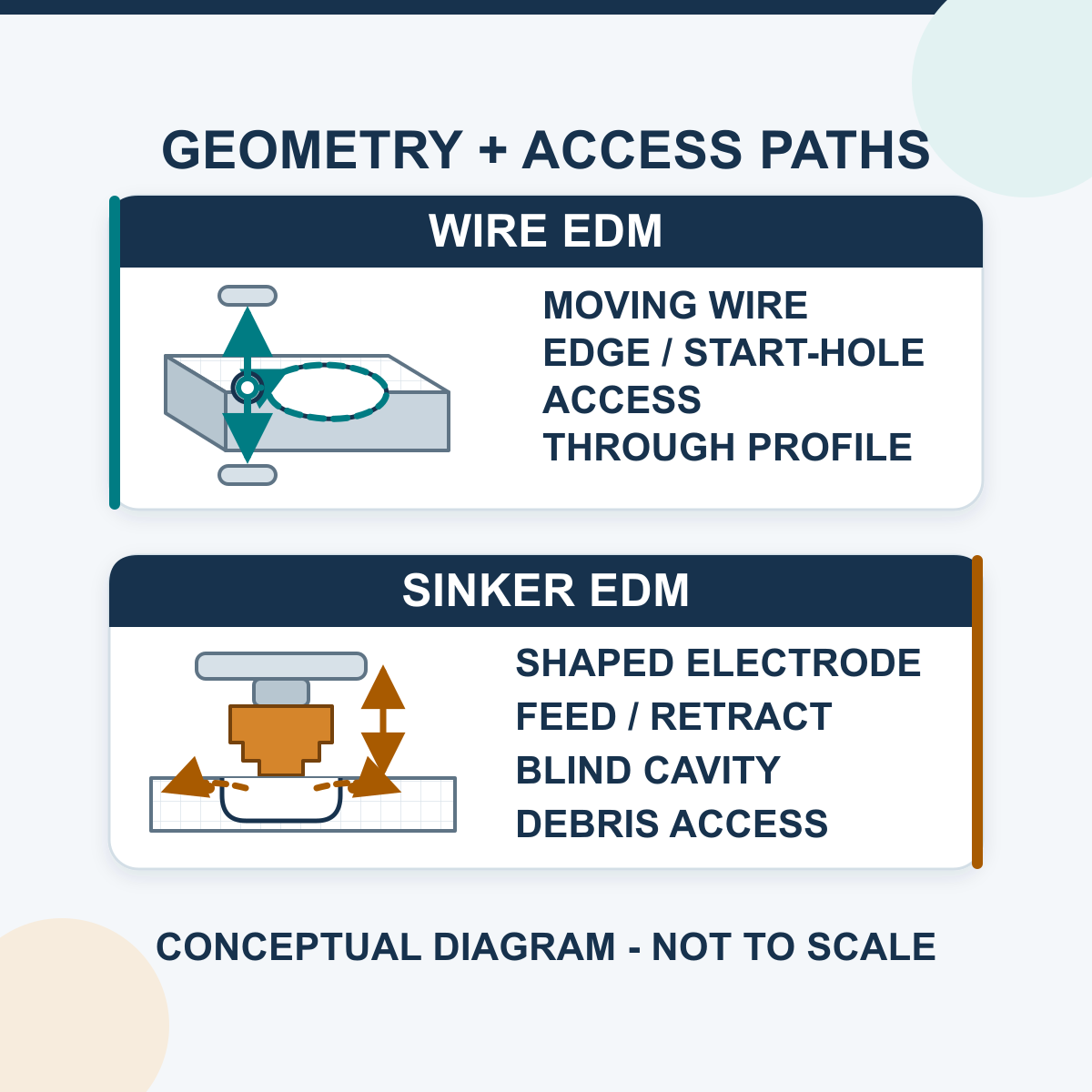
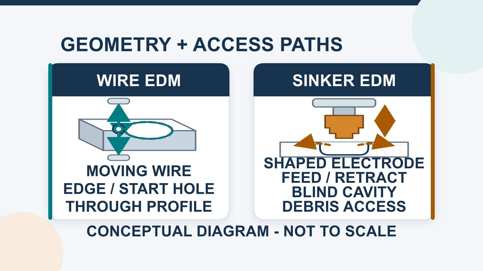
Start by evaluating Wire EDM when the required feature is a through contour that a moving wire can enter and follow; start by evaluating sinker EDM when the required feature is a blind cavity or three-dimensional form that must be reproduced by a shaped electrode. These are screening rules rather than an automatic final choice. Both processes use controlled electrical discharges and require a sufficiently conductive workpiece, but their electrode, access path, setup chain and geometry limits are different.
This is a process-selection guide, not a promise that one method is always faster, more accurate or less expensive. The drawing, workpiece, electrode or wire system, machine configuration, process stages and inspection plan must support the final decision.
Sinker EDM vs Wire EDM at a Glance
| Decision Field | Wire EDM | Sinker / Die-Sinking EDM |
|---|---|---|
| Electrode | Moving wire electrode guided through the cutting zone | Manufactured form electrode designed for the required cavity or feature |
| Typical result | Through contour, profile, slot or separated component | Blind cavity, recess, rib, pocket or three-dimensional formed detail |
| Entry and access | Outside profile may start from an edge; a closed internal profile normally needs a through start hole | Needs electrode/holder approach, clearance and a practical dielectric/debris route |
| Geometry boundary | The wire path and machine motion define the kerf; it is not the standard choice for a blind three-dimensional cavity | The electrode form, spark-gap allowance, motion and access define the cavity; it does not make an arbitrary sealed passage |
| Preparation | Program/offset, wire path, start access, workholding, guides, flushing and cut sequence | Electrode design/manufacture, undersize/offset, holder/datum, wear allowance, flushing and rough/finish sequence |
| Consumable behavior | Depends on the machine's wire architecture; HarsMarg's current single-cut and multi-cut families use reusable reciprocating molybdenum wire | The shaped electrode wears and may require compensation, redressing or more than one electrode |
| Acceptance evidence | Measured profile/size, straightness/taper as applicable, edge/slug result, surface and cut-stage record | Measured cavity size/form/depth, corner/radius result, electrode-wear record, surface and process-stage record |
How Wire EDM Creates a Through Contour
Wire EDM creates controlled discharges between a moving wire electrode and a conductive workpiece. The programmed relative motion guides the wire along a contour and leaves a kerf. Upper and lower guide conditions, wire behavior, workpiece thickness, flushing, offsets and the selected cut sequence can affect the result.
The wire must have a usable path through the cutting zone. An exterior profile may begin from an accessible edge. A closed interior profile normally requires a prepared start hole through which the wire is installed or threaded. The resulting core or slug, workholding stability and release sequence must be planned; a completed contour can change part support.
HarsMarg's current single-cut and multi-cut machines within the Wire EDM range use reusable molybdenum wire moving back and forth through the cut. Do not import brass-wire consumption, automatic-threading or disposal assumptions from another architecture, and do not extend this statement to a separately listed category without checking that machine's wire system. For the deeper benefits, limits and cut-stage evidence, use the separate Wire EDM advantages guide.
How Sinker EDM Creates a Blind or Formed Cavity
Sinker EDM creates controlled discharges between a shaped electrode and a conductive workpiece across a dielectric-filled machining gap. The electrode advances toward the workpiece while the control maintains a workable gap. Its form is transferred into the workpiece with the planned spark-gap allowance rather than as a perfect one-to-one copy.
For the initial routing decision, ask whether a practical shaped electrode and holder can approach the complete feature and whether dielectric and debris have a workable path. Electrode manufacture, wear compensation and the detailed rough/finish plan belong to the later sinker-process review rather than this first comparison.
HarsMarg groups its current die-sinking EDM range into ZNC and CNC die-sinking EDM categories. That classification begins a control and motion review; it does not by itself prove automatic electrode changing, probing, orbiting, unattended operation or a finished-part result.
What Both EDM Processes Share—and What They Do Not Prove
- Electrical conductivity is required: conductivity is necessary, but material grade/condition, geometry, gap stability, thermal behavior and economics still affect feasibility.
- No conventional cutting edge acts at the discharge interface: this can reduce cutter-pressure concerns, but it does not prove zero force, zero residual stress or zero distortion.
- EDM is thermal: recast/white layer, heat-affected material, microcracking or transferred material may need an agreed limit and inspection where functionally important.
- Electrodes change during use: wire condition/behavior and shaped-electrode wear must be controlled for the selected architecture and process.
- The process name is not an acceptance result: tolerance, surface texture, taper, straightness, corner radius, cycle time and cost require the actual model, setup, sequence and measurement context.
Compare the Complete Manufacturing Route
A useful comparison includes every operation needed to produce an accepted part:
- Define the feature. State whether it is an outside profile, closed internal through contour, blind cavity, recess, slot, rib or other formed detail.
- Check access. For Wire EDM, verify edge entry or start-hole location and full wire path. For sinker EDM, verify electrode/holder approach, clearance and debris escape.
- Count preparation work. Include start-hole drilling, wire installation and slug planning, or electrode design, manufacture, setup and wear allowance.
- Define the process sequence. Record the first/rough stage, any trimming or finishing stages, electrode/wire changes, inspection points and approved post-processing.
- Check the machine envelope. Confirm travel, table/tank/workpiece envelope, load, guide or holder clearance, axis/control functions, power supply and quoted options.
- Compare total accepted-part time and cost. Include programming, consumables, electrode manufacture, setup, machining, inspection, maintenance and rejected/reworked parts; do not compare isolated catalogue rates.
What to Send for a Sinker-vs-Wire Review
Send enough information to decide the process before selecting a model:
- 2D drawing and, where the cavity/form needs it, a 3D model with the relevant revision;
- workpiece material/grade and condition, overall dimensions, weight and accessible datum surfaces;
- feature type, depth or thickness, entry/approach direction, closed/open condition, minimum radii and required taper or draft;
- dimensional, form, position, edge, surface-texture and surface-integrity requirements with the intended inspection method;
- lot size, cycle target, accepted current route and any required sample or acceptance plan;
- destination, power supply and any genuinely required motion, handling or monitoring function.
Frequently Asked Questions
Can standard Wire EDM make a blind cavity?
Not as its normal geometry. The wire ordinarily passes through the workpiece and creates a through kerf. A blind three-dimensional cavity is generally a sinker EDM task using a shaped electrode.
Does sinker EDM need a start hole?
It does not need a hole for threading a wire. It still needs a practical electrode approach, holder clearance, dielectric/debris route and enough machine travel for the full setup.
Which process is more accurate or produces a finer surface?
Neither process wins universally. Compare the named HarsMarg model and configuration, feature geometry, electrode or wire, rough/first and finish/trim stages, setup, thermal condition and measurement method. Use a representative test when the requirement is critical or near a quoted limit.
Is Wire EDM always faster or cheaper than sinker EDM?
No. Wire EDM may need a start hole, careful slug control and multiple cut stages; sinker EDM may need one or more manufactured electrodes and cavity stages. Compare total time and cost for the accepted part, not an isolated cutting or erosion rate.
Can one machine perform both processes?
Do not assume so. Standard Wire EDM and sinker EDM use different electrode systems, work zones and motion/process arrangements. Any hybrid or optional function must be identified on the exact machine configuration and technical quotation.
Request a Drawing-Based Process Review
Compare the Wire EDM and die-sinking EDM families, then send the drawing and acceptance requirements to HarsMarg. HarsMarg can route the inquiry to the appropriate family, identify missing conditions and state which model functions or finished-part results require quotation review or a representative test.
Table of Contents
- Sinker EDM vs Wire EDM at a Glance
- How Wire EDM Creates a Through Contour
- How Sinker EDM Creates a Blind or Formed Cavity
- What Both EDM Processes Share—and What They Do Not Prove
- Compare the Complete Manufacturing Route
- What to Send for a Sinker-vs-Wire Review
- Frequently Asked Questions
- Request a Drawing-Based Process Review