EN
EN



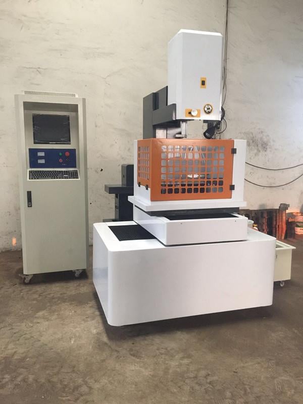
Wire EDM equipment is one machining route to evaluate for fine features in suitable conductive workpieces. It uses controlled electrical discharges to remove material along the wire's programmed path. For a fine-detail job, selection should begin with the actual material, feature geometry and acceptance requirements, rather than an assumption that wire EDM is always the most accurate or economical process.
The process does not use a conventional cutting edge in contact with the workpiece. That can be relevant when comparing routes for delicate features, but it does not prove that thermal effects, fixture movement or dimensional variation are absent. Review the proposed machine and cutting conditions, then inspect the finished features against the drawing.
Fine-Detail Accuracy and Acceptance
Finished Dimensions and Process Conditions
Specify the required dimensions, tolerances, datum references and inspection locations for each critical feature. Keep command resolution, machine positioning accuracy, repeatability and finished-part tolerance separate. A machine-motion specification or another manufacturer's example does not establish the result on your part.
Confirm the wire-motion system, approved wire grade and condition for the proposed equipment. A reciprocating-wire arrangement should not be described as continuously renewed fresh wire. Record the selected wire and process settings with the part result; neither wire renewal nor reuse establishes uniform accuracy throughout every cut.
If compensation or adaptive control is offered, ask what it measures, which settings it changes and the conditions under which it operates. Do not infer automatic material recognition or finished-part measurement from the function name. Check the actual feature dimensions after the agreed cutting route.
Surface Finish Edges and Surface Integrity
State the required roughness parameter, units and measurement method. Ra and Rz are different measures and should not be used interchangeably. Agree which surfaces and locations need inspection, and compare the result under the stated material, wire and cutting-pass conditions rather than using a universal finish range.
Review corner radii, slot width, wall height and the permitted edge condition on the drawing. Confirm how wire size, the proposed cutting allowance, access and workholding affect the route. A fine feature should not be accepted solely because its visible edge looks sharp or its surface looks smooth.
EDM can leave a recast layer or heat-affected region, so roughness and surface integrity require separate consideration. When reviewing wire EDM equipment, confirm any supported finishing passes and the required inspection or subsequent treatment. Do not assume a particular affected-layer thickness or an unaffected surface from non-contact cutting alone.
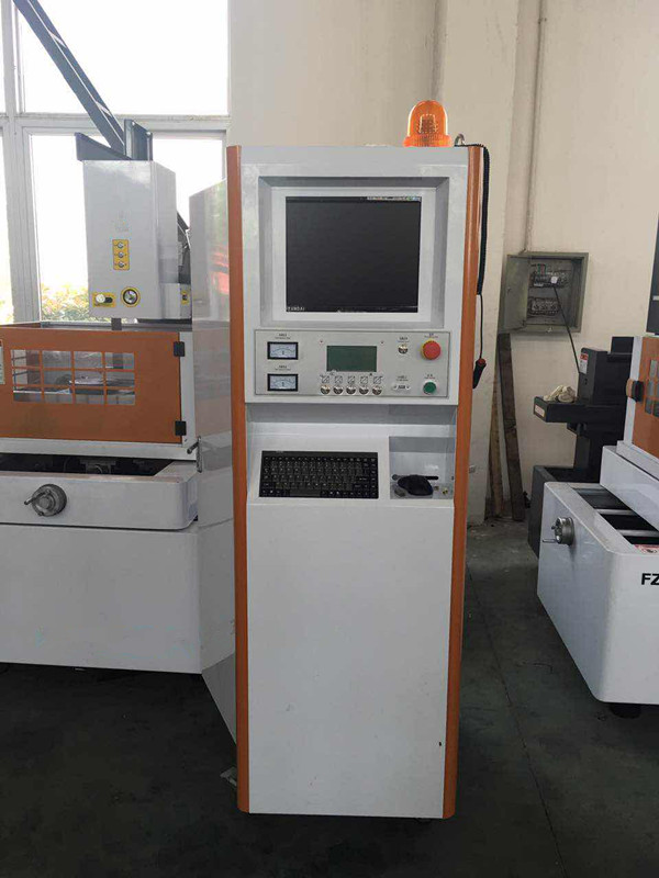
Material Suitability and Condition
Hardened Conductive Materials
Wire EDM may be considered for suitable conductive materials after hardening. Confirm the grade, heat-treatment state and proposed sequence before changing the route. This option does not establish equal cutting time or accuracy on hard and soft materials, or remove every subsequent treatment required by the part specification.
For thin walls or delicate features, review fixture forces, support, material condition and how the part will be retained as the cut progresses. Non-contact cutting is not a stress-free or distortion-free guarantee. Check the completed dimensions and any surface requirements after releasing or handling the workpiece as specified.
Where a workpiece contains welds, joints or different material states, identify the zones on the drawing. Confirm suitable settings and inspection for those transitions. Do not assume that one cutting condition produces the same speed, dimensions or surface result across every region.
Alloy and Composite Grades
Provide the exact alloy grade and condition rather than only a material-family name. For a critical application, include the drawing's acceptance and traceability requirements. An industry use of a material is not evidence that the quoted machine can produce the required feature or that the part has received industry approval.
For a composite, identify its constituents, structure and electrical conductivity before assessing the cutting route. Different grades and constructions should not be treated as equivalent. Confirm suitability and required surface results for the actual material; do not assume that every diamond or ceramic-based composite is wire EDM compatible.
A material's intended high-temperature use does not establish how a feature can be machined. Review the actual internal or external geometry, wire entry path, thickness and acceptance criteria. Cooling passages or other enclosed features need a feasible process route; their function alone does not demonstrate wire access.
Small Features and Wire Access
Axis and Taper Configuration
Confirm the controlled axes, guide arrangement and supported motions on the quoted machine. Review the upper and lower profiles and any taper at the required workpiece height. Taper control, a rotary attachment and simultaneous workpiece-orientation control are different capabilities, not interchangeable meanings of multi-axis.
For an internal contour, establish a usable wire-entry or starting-hole route and clearance throughout the cut. Review the fixture, support and cutting sequence with the actual geometry. A multi-axis label does not show that an enclosed passage, spiral or every internal surface can be completed in one setup.
Where reverse taper, an undercut or compound angles are required, check the proposed wire path against travel, guide and fixture limits. Identify any separate operation needed for inaccessible features. Select a route from the drawing rather than assuming that wire EDM removes all design or machining constraints.
Narrow Features and Workpiece Support
A fine-wire request must match the approved wire range, guides, threading arrangement and generator configuration. Review the feature width and required dimensions alongside wire size and the proposed discharge-gap allowance. An electrode diameter alone is not the finished slot width or a guaranteed part tolerance.
For a deep narrow slot, rib or tall wall, define the actual dimensions and measurement locations. Check workpiece support, flushing access, wire stability and handling of separated material. Non-contact cutting does not establish that a slender feature remains undamaged or dimensionally correct throughout the route.
If stacking or nesting is proposed, review alignment, clamping, access and inspection for the specific arrangement. Define which parts are cut together and how each is accepted. Compare accepted output and complete processing time; the arrangement does not by itself prove batch consistency or an economic advantage.
Process Control and Repeat Production
Monitoring Threading and Recovery
Identify which process signals the controller monitors and how it responds to changes. Keep electrical or axis feedback separate from actual measurement of finished dimensions and roughness. If in-process part measurement is proposed, confirm the instrument, accessible features and acceptance method.
If automatic threading or rethreading is supplied, establish its supported wire, starting-hole and recovery conditions. Plan how cores, consumables, alarms and failed retries are handled. Resuming a program at a recorded point does not guarantee an acceptable restart surface or a completed unattended batch.
Use monitoring information within the maintenance requirements for the actual machine. Confirm the meaning of warnings and the required response; a reminder is not evidence of a predictive system. Machine status or the absence of an alarm does not replace inspection of fine features.
Programming and Setup Verification
Confirm the supported drawing format, programming software and postprocessor for the controller. Check the resulting path against the datum, cutting allowance, fixture and sequence. File import, path generation or nesting software does not eliminate programming errors or establish the best surface result.
If automated alignment is proposed, identify the supplied measurement equipment and the datum-setting procedure. Confirm its limits for the actual feature and fixture. Do not assume laser, probing or vision equipment is fitted, or that automatic zero assignment eliminates setup errors.
A single fixture may reduce some transfers where all required features are accessible, but that arrangement still needs setup and acceptance checks. Review the relationships among features and any handling or finishing after cutting. One setup does not establish freedom from datum, dimensional or surface errors.
FAQ
What makes wire EDM equipment more accurate than conventional machining for fine details?
It is not automatically more accurate for every job. The non-contact discharge process can make wire EDM a route to consider for suitable conductive features, but the result depends on the drawing, machine and conditions. Compare actual finished dimensions and surface acceptance on equivalent parts; do not substitute a positioning specification for a demonstrated feature tolerance.
Can wire EDM equipment handle materials that are difficult to machine conventionally?
Suitability depends on the actual conductive grade, material state and workpiece geometry. Confirm the proposed wire, machine configuration and cutting conditions for that job. A hard-material or composite label is not a universal machinability guarantee, and the required dimensions and surface condition still need inspection.
How does wire EDM equipment maintain precision in complex three-dimensional geometries?
First confirm that the required features have a feasible wire path with the quoted axes, guides and workholding. Then verify the program, process settings and finished-part inspection. Axis count or adaptive control alone does not establish access to every surface, single-setup completion or a guaranteed tolerance on the geometry.
What advantages does wire EDM equipment offer for high-volume production of fine detail components?
Evaluate a repeat job using the actual configuration, complete processing time and agreed batch inspection. Record accepted, rejected and reworked parts along with interruptions and maintenance. Reusing a program or cutting a stack does not prove identical results throughout a run, and productivity or cost benefits need comparable production records.
Table of Contents
- Fine-Detail Accuracy and Acceptance
- Material Suitability and Condition
- Small Features and Wire Access
- Process Control and Repeat Production
-
FAQ
- What makes wire EDM equipment more accurate than conventional machining for fine details?
- Can wire EDM equipment handle materials that are difficult to machine conventionally?
- How does wire EDM equipment maintain precision in complex three-dimensional geometries?
- What advantages does wire EDM equipment offer for high-volume production of fine detail components?