EN
EN



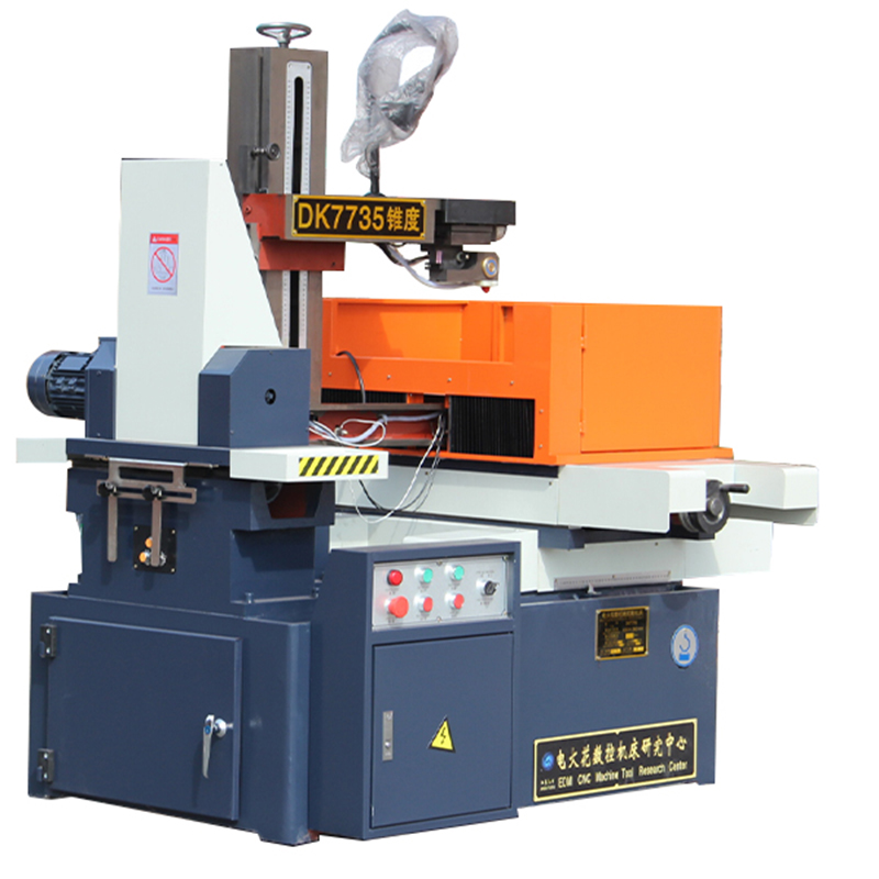
Do not set up Wire EDM for a new material by copying a universal current, voltage, pulse, tension or flushing recipe. First confirm that the workpiece has a suitable electrically conductive path. Then identify the exact grade and condition, reproduce the production thickness and risk geometry in a representative sample, begin from a condition approved for the selected machine and change only controlled variables until the measured result is acceptable.
HarsMarg's current single-cut and multi-cut Wire EDM machines use reusable molybdenum wire stored on a wire drum and transported back and forth through the cutting zone. Advice written for one-way consumable brass or coated wire should not be transferred to this system. Wire diameter, wire transport, tension, working fluid and electrical conditions must come from the selected model's manual, controller data or an approved process sheet.
This article focuses on material-specific trial planning. For the general sequence covering the drawing, fixture, wire path, working fluid, program, datum and first-piece checks, use the Wire EDM setup checklist.
Safety boundary: Only trained personnel should operate or adjust the machine. Use the model manual and site procedures for guarding, electrical isolation, working-fluid handling, loading and maintenance. Do not change protected generator, axis or service parameters as part of an informal material trial.
What Changes When the Workpiece Material Changes?
A material name is the start of the process plan, not the process plan itself. Electrical conductivity, composition, heat treatment, binder, coating and surface condition can affect discharge behavior or the final surface. Thickness, contour, changing part height, flushing access, fixture support, wire condition and the required inspection result can be equally important.
| Material family | Confirm before the trial | Represent in the sample | Inspection priority |
|---|---|---|---|
| Conductive steel and tool steel | Exact grade, heat-treatment state, hardness if relevant, scale/coating and residual-stress concern | Production thickness, heat-treated condition, corner and slug-release behavior | Size, profile, straightness or taper, roughness when specified, discoloration/corrosion and stability after release |
| Copper and brass | Exact alloy and temper, electrical-contact surface, thickness and thin-feature risk | Representative section, narrow webs, corners and the real fixture/contact arrangement | Feature size, kerf/offset result, edge condition, flatness and wire/process stability |
| Aluminum alloy | Alloy and temper, oxide/coating, section stiffness, cleaning and post-cut handling requirements | Production thickness, thin walls or flexible features and the intended support method | Distortion, edge/surface condition, staining or corrosion after cleaning, size and profile |
| Titanium and nickel-based alloy | Exact grade, heat treatment, service or regulated-part requirement and permitted surface-alteration limit | Same grade/condition, thickness, corner and finish-pass plan | Drawing dimensions plus specified surface-integrity, recast-layer, contamination or metallurgical checks |
| Conductive carbide or sintered material | Grade, binder type/content, conductivity, porosity and fluid/corrosion restrictions | Same grade and binder, production thickness, edge geometry and planned fluid exposure | Edge chipping, cracking, size, roughness and customer-defined binder depletion or surface-integrity criteria |
The table is a planning guide, not a claim that every grade in each family is already qualified on every HarsMarg model. Suitability and the final process require review of the actual material, drawing, machine configuration and sample result.
1. Pass the Material Suitability Gate
Wire EDM removes material through electrical discharges between the wire electrode and workpiece, so the job needs a sufficiently conductive path. Do not approve a material from hardness alone. Record the exact specification and grade, supplier or mill certificate when available, heat treatment or temper, coating, binder and any known anisotropy, porosity or composite construction.
Confirm where the machine's work connection will contact clean conductive material. Paint, oxide, scale, plating, contamination, bonded layers or an interrupted conductive phase can change contact or process behavior. If the part is a ceramic composite, PCD, carbide or another sintered material, verify conductivity and binder information instead of assuming that the family name guarantees Wire EDM compatibility.
If a material or coating creates a health, fire, chemical, dust, fluid-reaction or waste-handling concern, obtain the current safety data and follow the material supplier's and site's controls before a trial. This article does not establish a safe process for hazardous or regulated materials.
2. Design a Representative Sample Cut
Use production stock from the same lot when practical. Otherwise document why the coupon is a valid substitute. Match the production heat-treatment state or temper, relevant surface condition and the actual current path. A coupon made from annealed stock does not validate a heat-treated production part if heat treatment is one of the uncontrolled differences.
Reproduce the maximum or critical workpiece thickness, including stepped or interrupted sections. Include geometry that tests the real risk: a straight segment for size and straightness, the required corner radius, a lead-in/lead-out or start hole where applicable, a thin web if the drawing contains one, and a controlled slug-release method. Use the intended fixture support and fluid access rather than testing a freely accessible flat coupon when production flushing will be restricted.
Define acceptance before cutting. State the required feature size, profile or position tolerance, straightness/taper, corner, kerf or offset result and surface roughness when specified. If surface integrity matters, state the required examination and limit; “good surface” is not a measurable criterion.
3. Control and Record the Variables
| Variable group | Record for every trial | Why it matters |
|---|---|---|
| Workpiece | Grade/standard, lot, heat treatment or temper, hardness if relevant, thickness map, coating and pre-cut condition | Makes the sample traceable and separates a material change from a geometry change |
| Machine and controller | Model, controller, relevant configuration, program revision and selected approved condition/reference | Prevents a condition from being treated as portable across different generators or functions |
| Molybdenum-wire system | Wire specification/diameter, wire lot or source, prior-use condition, drum winding, approved tension and transport settings | Wire condition and movement affect stability and repeatability |
| Working fluid and flushing | Approved product, control measurement when required, filtration/maintenance status, nozzle arrangement, access and observed debris removal | Gap condition and debris removal depend on both fluid condition and geometry |
| Cut strategy | Single-cut or multi-cut plan, first-cut and trim sequence, controller condition, wire offset/compensation, start/exit method and taper if used | The final result belongs to the complete pass schedule, not one isolated setting |
| Fixture and environment | Datum, supports, clamps, electrical connection, room/fluid condition when relevant, stabilization time and slug support | Separates material response from movement, distortion or measurement drift |
| Inspection | Instrument, calibration status, datum, sampling locations, temperature/conditioning when required and raw measured values | Makes the acceptance decision reproducible rather than visual or subjective |
4. Build the Trial Around the Material Family
Conductive steel and tool steel
Record the exact steel grade and heat-treatment state. Wire EDM can be evaluated for conductive hardened steels, but “hardened steel” does not define one electrical condition or one result. Scale, coating, decarburized layers and residual stress can also distinguish the sample from the production part.
Inspect the feature before and after slug release when distortion is a risk. For a multi-cut route, measure the final result only after the complete approved trimming sequence. If the part has a corrosion or surface-integrity requirement, specify the allowed condition and post-cut cleaning instead of assuming a normal visual finish is sufficient.
Copper and brass
Identify the alloy and temper rather than using “copper” or “brass” as the full material description. Check the electrical contact surface and represent thin webs, narrow slots or flexible sections in the coupon. Do not infer that high conductivity automatically requires a particular current or pulse direction; validate the selected controller condition on the actual section.
Record size, profile, corner and edge condition, plus the wire offset that produced the result. If a thin feature can move when the slug is released, include a support and release plan in the trial.
Aluminum alloy
Record the aluminum alloy, temper, coating or oxide condition and production thickness. Establish a clean, reliable electrical connection and use a fixture that supports flexible walls without distorting them. Confirm that the working fluid and post-cut cleaning procedure are acceptable for the exact alloy and customer requirement.
Inspect dimensional change, flatness or profile after the part is removed from the fixture. Also examine the cleaned surface after the agreed hold time when staining or corrosion is a concern. Do not publish or approve a universal “aluminum setting”; retain the qualified condition with its sample evidence.
Titanium and nickel-based alloy
Use the exact grade and heat treatment. State whether the part is a general industrial component or is subject to an aerospace, medical or other regulated specification. Wire EDM capability alone does not establish compliance for a regulated part.
Where the drawing or customer specification controls recast layer, heat-affected condition, microcracking, contamination or other surface-integrity characteristics, include the required metallurgical examination in the sample plan. A dimensional pass is not proof that a separate surface-integrity requirement has been met.
Conductive carbide and sintered material
Confirm the exact grade, conductive phase and binder composition/content. Water exposure can be a material-integrity concern for some WC-Co carbides because the cobalt binder may be depleted. Do not assume that a condition qualified on tool steel is suitable for carbide, and do not claim that every conductive carbide is approved.
Agree on inspection for edge chipping, cracking, size, roughness and binder/surface condition. When the customer's limit cannot be verified with normal shop measurement, arrange the required specialist or laboratory method before production release.
5. Validate Single-Cut and Multi-Cut Jobs Differently
For a process overview, see Single-Cut vs Multi-Cut Wire EDM. Both HarsMarg structures use reciprocating molybdenum wire, but their release evidence is not the same.
| Validation point | Single-cut job | Multi-cut job |
|---|---|---|
| Trial route | Test the planned one-cut production condition and offset | Test the complete first-cut and trimming-pass sequence in the intended order |
| Intermediate data | Record the cut condition, stability and first-piece measurement | Keep first-cut and each trimming-pass condition/offset traceable; do not describe the first-cut result as the final result |
| Release decision | Release only if the one-cut result meets the agreed requirement | Release only after the full sequence meets dimensional, finish and surface-integrity requirements |
6. Run a Controlled Trial and Lock the Approved Process
- Select a bounded baseline. Use a condition supplied for the exact HarsMarg model/controller or a documented prior job with a comparable material and section. Record why it is relevant.
- Cut the representative coupon. Observe discharge stability, flushing/debris behavior, reciprocating wire transport, abnormal sound and wire breaks. Stop and investigate abnormal behavior by the approved machine procedure.
- Measure the defined outputs. Record the raw dimensional and surface results rather than only “pass” or “fail.” Inspect after the complete pass sequence and required cleaning/conditioning.
- Change one controlled factor. If the result misses the target, adjust only a variable permitted by the model/controller documentation so the effect can be interpreted. Do not conceal a fixture, fluid or wire-path problem with electrical changes.
- Repeat when risk requires it. One coupon may establish feasibility but not production repeatability. Decide the sample quantity from material variability, part value, tolerance, inspection risk and production volume.
- Release a traceable process sheet. Lock the approved material, machine, wire, fluid, fixture, program, offsets, pass sequence and inspection plan under revision control.
7. Measure More Than Cutting Time
Cycle time matters, but it cannot be the only trial result. Measure the features defined by the drawing using calibrated equipment and a documented datum. When the job is thickness-sensitive, sample the top, middle and bottom or use another method capable of detecting straightness/taper. When roughness is specified, record the instrument, parameter, cutoff/filter and sampling direction/location so the value can be reproduced.
Inspect the cleaned surface and edge condition. A regulated or fatigue-critical part may require metallography, recast-layer evaluation, microhardness, crack inspection, contamination analysis or another customer-defined test. Use the specified method and acceptance limit; do not infer these results from dimensional accuracy or a visual inspection.
Record process interruptions, wire breaks, abnormal arcing/shorting indications, flushing limitations and post-cut distortion. These observations help determine whether a result is robust enough for production rather than merely achievable once.
What to Send for a Material-Specific Wire EDM Review
For a technical review or sample-cut discussion, send the following information through the HarsMarg inquiry form:
- workpiece material name, standard and exact grade, plus a certificate or composition when available;
- heat treatment, temper, hardness and coating/surface condition where relevant;
- 2D/3D drawing with overall size, thickness variation, datum and the features to wire-cut;
- part and fixture weight, planned orientation, start-hole/open-cut information and access restrictions;
- required tolerance, profile/position, taper, minimum inside radius, kerf/slot and surface roughness;
- surface-integrity, recast-layer, crack, contamination, corrosion or regulated-industry requirements;
- quantity, target cycle time if applicable and whether representative sample material is available;
- destination country, power supply and any loading, automation or inspection requirement.
HarsMarg can then compare the job with the current Wire EDM range and identify which machine capacity and trial evidence need to be confirmed. A quotation should not promise speed, accuracy or finish until the actual material, geometry and required result have been reviewed.
FAQ
Can the same Wire EDM parameters be used for every grade in one material family?
No. Grade, composition, heat treatment, thickness, geometry, working fluid, flushing, wire condition, pass plan and target result can all change the qualified process. Reuse a condition only when its applicability is documented and confirm it with a controlled first piece or sample.
Can Wire EDM cut every hard material?
No. Hardness alone does not establish suitability. The workpiece needs a suitable electrically conductive path, and the exact grade, coating, binder and surface-integrity requirements must be reviewed. A nonconductive ceramic or composite should not be promised without a proven conductive process route.
Should brass or coated wire be selected for a difficult HarsMarg job?
Do not apply that advice to the current HarsMarg reciprocating-wire range. These machines use reusable molybdenum wire. Select the model-approved molybdenum-wire specification and diameter for the actual machine and validate it with the workpiece and pass plan.
Does the material family determine flushing pressure?
No. Material is only one input. Part height, changing cross-section, contour, start/exit condition, fixture obstruction, nozzle access, working-fluid condition and wire behavior also affect debris removal and stability. Use the model's approved procedure and validate the actual geometry rather than publishing one pressure by material.
What should be changed first when a sample result is poor?
First rule out an incorrect program, offset, datum, fixture, electrical contact, wire path, worn or damaged wire, working-fluid condition and flushing obstruction. Then compare the result with the approved baseline and change one permitted process variable at a time. Record every revision and measurement.
Table of Contents
- What Changes When the Workpiece Material Changes?
- 1. Pass the Material Suitability Gate
- 2. Design a Representative Sample Cut
- 3. Control and Record the Variables
- 4. Build the Trial Around the Material Family
- 5. Validate Single-Cut and Multi-Cut Jobs Differently
- 6. Run a Controlled Trial and Lock the Approved Process
- 7. Measure More Than Cutting Time
- What to Send for a Material-Specific Wire EDM Review
-
FAQ
- Can the same Wire EDM parameters be used for every grade in one material family?
- Can Wire EDM cut every hard material?
- Should brass or coated wire be selected for a difficult HarsMarg job?
- Does the material family determine flushing pressure?
- What should be changed first when a sample result is poor?