EN
EN



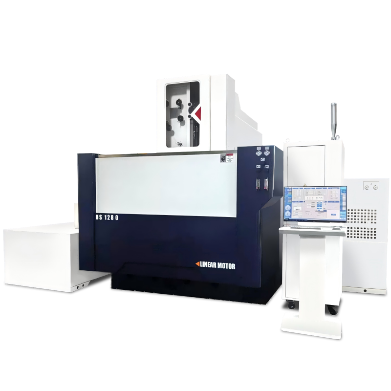
A reliable Wire EDM setup starts by matching the drawing, workpiece and required result to the selected machine before any cutting parameter is entered. Confirm the material and thickness, part size and weight, datum, contour, tolerance, surface-finish target and cutting sequence. Then verify the fixture, molybdenum-wire path, working fluid, program, work coordinate and inspection plan in a controlled order.
HarsMarg's current single-cut and multi-cut Wire EDM machines use reusable molybdenum wire stored on a wire drum and moving back and forth through the cutting zone. The exact wire tension, wire speed, working-fluid condition and electrical parameters must come from the selected model's manual, controller data and an approved process sheet. A numerical setting copied from another machine type is not a safe starting point.
Safety note: This checklist supports job preparation; it does not replace the machine manual, operator training, site safety procedures or maintenance instructions. Only trained personnel should operate the machine. Never bypass a guard or interlock, and refer electrical, axis-calibration and repair work to qualified personnel.
Wire EDM Setup Checklist at a Glance
| Stage | Verify Before Cutting | Record |
|---|---|---|
| 1. Job definition | Drawing revision, units, material, hardness if relevant, dimensions, thickness, weight, datum, tolerance, roughness, taper and quantity | Approved drawing and job revision |
| 2. Machine fit | X/Y travel, worktable, table-load limit, maximum workpiece thickness, required taper and controller capability | Machine model and confirmed configuration |
| 3. Workholding | Clean support, stable clamping, cutting clearance, accessible wire path, reliable datum and workpiece electrical connection | Fixture reference and clamping arrangement |
| 4. Wire system | Correct molybdenum-wire specification, usable wire condition, correct drum and guide path, suitable tension and transport settings | Wire diameter, wire condition and approved settings |
| 5. Working fluid | Approved fluid, adequate level, acceptable condition, filtration and stable flushing without excessive wire deflection | Fluid product, condition and maintenance status |
| 6. Program and parameters | Units, scale, contour, start point, offset, direction, taper, cut count and a validated condition for the material and thickness | Program revision and parameter-set reference |
| 7. Datum and path | Work coordinate, reference surfaces, approach, cutting clearance and a graphical or non-cutting path check when supported | Zero-setting method and measured references |
| 8. Trial and release | Stable discharge, wire transport, flushing and first-piece results before the production batch is released | Measured result, corrections and approval |
1. Confirm the Job Before Setting Up the Machine
Begin with the latest approved drawing, not an old program name or a verbal description. Check the drawing revision, units, material grade, heat-treatment or hardness information when relevant, maximum X/Y dimensions, thickness, weight and quantity. Confirm which surfaces establish the datum and which features require an internal start hole.
Separate the quality requirements instead of using the word “precision” alone. Record dimensional tolerance, profile or position requirement, corner radius, taper and surface roughness as different items. If the drawing does not state how a feature will be inspected, agree on the measurement method before production.
The workpiece must be electrically conductive for Wire EDM. Coatings, scale, contamination or interrupted surfaces may also affect electrical contact and process stability, so they should be identified during planning rather than discovered after cutting starts.
2. Confirm That the Selected Machine Fits the Complete Setup
Compare the job with the selected machine's published X/Y travel, worktable dimensions, table-load limit and maximum workpiece thickness. Include the fixture, clamps and practical clearance; do not compare only the finished part size. Also confirm the required taper, available axes, controller functions, wire specification and local power configuration for the actual quoted machine.
Before the shift or job begins, complete the inspections required by the model manual and the site's preventive-maintenance routine. Confirm that required guards and covers are in place, scheduled safety checks are current, and the working area is clean. Inspect accessible wire-path components, fluid delivery points and the table area for visible damage, contamination or an obstruction. Do not change backlash compensation, axis calibration, generator calibration or protected service parameters as part of a normal job setup.
3. Clean, Support and Clamp the Workpiece
Clean the workpiece and fixture contact surfaces before alignment. Remove loose burrs, chips, rust or contamination that could prevent stable seating, alter the datum or interrupt the electrical connection. Support the part so it cannot rock, sag or move when the wire reverses direction or the fluid flows through the cutting zone.
Place clamps outside the programmed wire path and allow clearance for the guides, nozzles and any taper movement required by the program. Use enough support to prevent distortion, but do not tighten a thin or stress-sensitive part so aggressively that its shape changes. Confirm the electrical connection to the workpiece by the method specified for the machine; fixture material alone should not be assumed to provide a reliable connection.
Establish the datum from clean, stable reference surfaces. If the part will be removed and returned to the machine, document the fixture location and reference method so the setup can be reproduced.
4. Check the Molybdenum Wire, Drum and Wire Path
Use the molybdenum-wire diameter and specification approved for the selected model and job. Check the exposed wire for contamination, kinks, flattening, abnormal wear or damage. A wire that has already been used must be judged by the shop's replacement rule and the quality requirement of the job; “reusable” does not mean that its condition can be ignored.
Thread the wire only by the route defined in the machine manual. Confirm that it sits correctly through the wire guides, rollers and cutting zone and that the drum has a suitable winding condition and travel margin. No part of the fixture or workpiece should obstruct the intended wire path.
Set wire tension and wire transport from the qualified process sheet for that machine, wire and cut. There is no trustworthy HarsMarg-wide tension value for every model and application. Too little or too much tension can change wire behavior or contribute to a break, but the correct adjustment must be validated on the specific equipment rather than guessed from a generic online range.
5. Prepare the Working Fluid and Flushing
Use the working fluid approved for the selected reciprocating-wire machine. Check the tank level, visible condition, circulation and filtration according to the machine and fluid-supplier instructions. Record the product and its condition, plus concentration or another control measurement if the approved fluid procedure requires one.
Position the fluid delivery so debris can be removed from the cutting gap and the process remains stable. Flow should reach the cutting zone without pushing the wire out of its intended path. The practical arrangement depends on part thickness, contour, fixture obstruction and whether the cut is open or poorly flushed. Do not copy a deionized-water conductivity range or high-pressure flushing value from a different Wire EDM architecture.
6. Verify the Program, Offset and Electrical Condition
Before selecting a condition, confirm the program revision, units, scale, coordinate orientation, contour direction, start position and any lead-in or lead-out. Review the programmed wire offset or kerf compensation against the wire, cut sequence and validated process. For an internal closed profile, also confirm the start-hole location and enough clearance for threading.
Select electrical and motion settings from a qualified condition for the workpiece material, thickness, wire and required result. Controller names and available functions vary by machine configuration, so use the documentation supplied with the quoted controller. Do not enter an arbitrary peak current, pulse duration, duty cycle, wire speed or tension value because it appeared in an unrelated article.
Where the controller supports graphics, simulation or another non-cutting path check, use it to look for an incorrect unit, reversed contour, offset error, clamp collision or insufficient travel. A successful screen check does not replace a physical clearance check at the machine.
7. Establish the Work Coordinate and Recheck Clearance
Set the work coordinate from the datum defined in the drawing and setup plan. Use the locating method supported by the selected machine and document the measured reference. Recheck part orientation, program origin and sign direction before cutting.
Move through the required setup verification procedure at safe conditions and check clearance around the full planned work area. Account for the fixture, clamps, wire guides, nozzles and taper movement. If the datum, offset or clearance cannot be verified, stop and correct the setup instead of relying on a trial production part.
8. Make a Controlled Trial Cut and Inspect the Result
For a new material, unfamiliar thickness, new fixture or critical drawing requirement, plan a sample cut or a controlled first piece. During the cut, watch for unstable discharge, abnormal sound, inconsistent flushing, excessive vibration, poor wire travel or repeated wire breakage. Stop according to the machine procedure if the process becomes abnormal; do not compensate for an unknown fault by changing several settings at once.
Inspect the first piece against the defined drawing requirements. Measure the feature size and relevant profile, taper or corner condition with a suitable method. Check surface roughness only when it is a specified requirement and the shop has an appropriate instrument and sampling method. Record the original result and every correction so the final setup can be reproduced.
How Does Setup Differ for Single-Cut and Multi-Cut Wire EDM?
The common preparation steps are the same, but the cutting plan and release criteria are different. For a fuller process comparison, see Fast vs Medium-Speed Wire EDM: Single-Cut vs Multi-Cut.
| Setup Point | Single-Cut Wire EDM | Multi-Cut Wire EDM |
|---|---|---|
| Cutting plan | One planned production cut must satisfy the agreed drawing and finish requirement | A first cut is followed by the required trimming cuts |
| Offset and allowance | Use the validated offset for the one-cut process | Plan the first-cut allowance and the offset for each trimming pass; do not invent one universal allowance |
| Parameter selection | Select the qualified condition for the material, thickness, wire and one-cut target | Confirm the correct condition and order for the first cut and every trimming pass |
| Verification | Release production only when the first piece meets the one-cut requirement | Distinguish first-cut results from final results and inspect after the completed trimming sequence |
| Cycle-time record | Record the complete setup and one-cut cycle | Record the first cut and all trimming passes; total cycle time includes every pass |
Multi-cut capability provides a controlled route for trimming, but it does not automatically guarantee the same tolerance or roughness on every part. The result still depends on the material, thickness, contour, wire condition, working fluid, settings, fixture, allowance, number of cuts and inspection method.
What Should Be Recorded for a Repeatable Setup?
- Machine model, controller and relevant configuration
- Part number, drawing revision, units and program revision
- Material grade, hardness when relevant, workpiece dimensions, thickness and weight
- Fixture reference, clamp locations, datum and zero-setting method
- Molybdenum-wire specification, diameter and condition
- Wire transport and tension settings from the approved process sheet
- Working-fluid product and condition, plus concentration or control measurement when applicable
- Flushing arrangement and any obstruction caused by the part or fixture
- Parameter-set reference, wire offset, cut sequence and trimming-pass plan
- First-piece measurements, surface result when required, corrections and release approval
A setup record is useful only when its terms are unambiguous. Do not label a number merely as “accuracy” or “speed.” State whether it is a feature deviation, positioning result, surface roughness, programmed feed, cutting rate or total cycle time, and record the conditions under which it was measured.
Stop the Setup and Investigate If
- The drawing revision, units, material or inspection requirement is unclear.
- The complete workpiece-and-fixture setup may exceed travel, table load or allowable thickness.
- The datum, electrical connection, clamp security or cutting clearance cannot be verified.
- The wire, guides, rollers, drum winding or fluid system shows visible damage or abnormal condition.
- The program, offset, cut count or parameter set does not match the approved process plan.
- A guard, cover, interlock or required safety check is not in its approved condition.
- The trial cut shows repeated wire breaks, unstable discharge, unexpected geometry or a result outside the agreed requirement.
Information to Send HarsMarg Before a Technical Recommendation
For model selection or a sample-cut review, provide:
- Workpiece material, grade and hardness when relevant
- Drawing and maximum X/Y dimensions, thickness and weight
- Contour, smallest corner radius, taper and start-hole requirements
- Target dimensional tolerance and surface roughness
- Expected quantity, batch size and cycle-time objective
- Whether the process should be evaluated as single-cut or multi-cut
- Local voltage and frequency, installation location and destination country
- Required sample-cut, measurement record or acceptance method
Review the complete Wire EDM machine range, compare the single-cut models and multi-cut models, or send the job information to HarsMarg for a configuration review. Final settings, capacity and expected performance should be confirmed for the quoted model and sample.
Frequently Asked Questions
Is there one wire-tension value for every HarsMarg Wire EDM machine?
No. Tension must match the selected model, molybdenum-wire specification, cutting sequence and qualified process. Use the model manual and approved process sheet rather than a universal online value.
Should every HarsMarg Wire EDM use a deionized-water conductivity setting?
No universal conductivity value has been confirmed for the HarsMarg reciprocating-wire range. Use the manufacturer-approved working fluid and its control procedure for the selected machine. Do not copy a value from a different Wire EDM architecture.
Can the same setup be used for single-cut and multi-cut jobs?
The machine, workholding, wire, fluid and datum checks follow the same principles, but the process plans differ. A single-cut job has one planned production cut. A multi-cut job requires a first cut plus confirmed trimming passes, each with its own qualified condition and offset.
When is a sample cut necessary?
A sample cut is appropriate when the material or thickness is new, the fixture or contour is unusual, the drawing requirement is critical, or the buyer and supplier need an agreed result before production or purchase. The sample plan should define what will be measured and by which method.
Should an operator adjust axis compensation or calibrate the generator during setup?
Not as a normal job-setting step. Protected compensation, axis calibration, electrical calibration and repair work should follow the machine's maintenance procedure and be performed only by authorized, qualified personnel.
Next Step
Prepare the drawing, material, workpiece dimensions and weight, target tolerance and roughness, required cut sequence, quantity and local power supply. HarsMarg can then identify the suitable model range and define the technical points that should be confirmed in a quotation or sample-cut plan.
Table of Contents
- Wire EDM Setup Checklist at a Glance
- 1. Confirm the Job Before Setting Up the Machine
- 2. Confirm That the Selected Machine Fits the Complete Setup
- 3. Clean, Support and Clamp the Workpiece
- 4. Check the Molybdenum Wire, Drum and Wire Path
- 5. Prepare the Working Fluid and Flushing
- 6. Verify the Program, Offset and Electrical Condition
- 7. Establish the Work Coordinate and Recheck Clearance
- 8. Make a Controlled Trial Cut and Inspect the Result
- How Does Setup Differ for Single-Cut and Multi-Cut Wire EDM?
- What Should Be Recorded for a Repeatable Setup?
- Stop the Setup and Investigate If
- Information to Send HarsMarg Before a Technical Recommendation
-
Frequently Asked Questions
- Is there one wire-tension value for every HarsMarg Wire EDM machine?
- Should every HarsMarg Wire EDM use a deionized-water conductivity setting?
- Can the same setup be used for single-cut and multi-cut jobs?
- When is a sample cut necessary?
- Should an operator adjust axis compensation or calibrate the generator during setup?
- Next Step