EN
EN



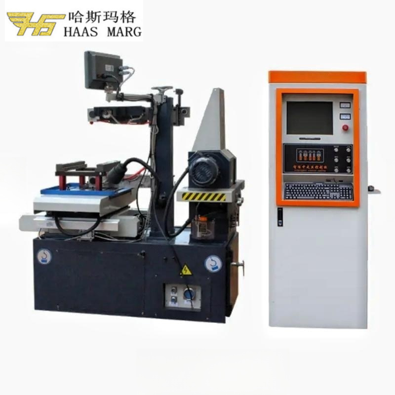
The reliable way to improve Wire EDM cutting speed is to optimize a repeatable process, not to maximize one electrical setting. Define the material, thickness, contour, tolerance, surface finish and cutting sequence; record a stable baseline; then change one approved variable at a time. Compare the complete time required to produce an accepted part, not only the highest feed or cut-area rate displayed during one section of the first cut.
HarsMarg's current single-cut and multi-cut Wire EDM machines use reusable molybdenum wire stored on a wire drum and moving back and forth through the cutting zone. Advice written for a one-way disposable-wire machine—including its consumable selection, feed rates, deionized-water conductivity values or automatic functions—must not be transferred to this equipment unless the supplied model and manual explicitly support it.
Operating note: Cutting parameters, wire tension, wire transport, working-fluid control and maintenance limits are model- and controller-specific. Only trained personnel should make adjustments permitted by the machine manual or an approved process sheet. Stop and investigate repeated wire breaks, unstable discharge, abnormal motion, damaged components or a result outside the agreed requirement.
First Define What “Cutting Speed” Means
Wire EDM speed can be reported in several ways. A useful comparison must name the metric and the conditions. Do not convert one figure into another unless the geometry and measured time are known.
| Metric | What It Describes | What Must Be Reported With It |
|---|---|---|
| Programmed or actual path feed | Movement along the programmed contour, commonly expressed in mm/min | Material, cut height, contour, machine condition and whether the value is programmed, displayed or measured |
| Cut-area rate | Cross-sectional area cut per unit time, commonly expressed in mm²/min | Specimen, material, effective cut height, contour length, active cutting time and cut number |
| Active cutting time | Elapsed time while the machine is executing the defined cut | Start and end points, first cut or trimming cut, pauses, recovery and any interrupted sections |
| Accepted-part cycle time | Total time required to obtain a part that passes the agreed inspection | Setup, threading, first cut, every trimming cut, wire-break recovery, handling, inspection, rework and rejected parts |
For a uniform-height test cut, cut-area rate may be calculated from the measured contour length multiplied by the effective cut height and divided by active cutting time. If the section height changes, state the actual specimen and calculation method instead of applying a uniform-height formula. Where a current HarsMarg multi-cut product page lists a specified maximum cutting speed of ≥150 mm²/min, treat it as a model-specific, conditioned cut-area-rate reference—not as a guaranteed rate or delivery-time basis for an untested customer part.
A Controlled Workflow for Improving Wire EDM Speed
1. Fix the Quality Target Before Optimizing Time
Start with the latest drawing and separate the requirements: dimensional tolerance, profile or position, corner radius, taper, surface roughness and any heat-affected or recast-layer requirement that the customer actually specifies. Record the material grade and hardness when relevant, maximum part dimensions, cut height or thickness, weight, contour length, start-hole plan and quantity.
A trial is not faster if the part fails inspection or needs extra trimming and rework. Use the same inspection method and sampling points for the baseline and every comparison. If the measurement method is not agreed, resolve it before changing the process.
For the related dimensional-control and measurement workflow, see the Wire EDM accuracy and inspection checklist.
2. Confirm the Machine, Controller and Cutting Sequence
Check that the selected model covers the complete workpiece-and-fixture setup: X/Y travel, worktable, table load, maximum workpiece thickness, taper, wire specification and required controller functions. Then decide whether one planned cut can meet the requirement or whether the job needs a first cut followed by trimming cuts.
Select the starting electrical and motion condition from the controller data, model manual or an approved condition already validated for the material, thickness, molybdenum wire and quality target. Do not begin with a generic current, voltage, pulse-on, pulse-off, wire-speed or tension value copied from another machine. Do not assume that an automatic optimization function is available unless it is confirmed on the quoted controller and configuration.
3. Establish a Repeatable Baseline
Before trying to go faster, run a stable baseline and record:
- Machine model, controller and relevant configuration
- Material grade, hardness when relevant, workpiece dimensions and effective cut height
- Contour, start position, taper, corner requirements and total programmed cut length
- Molybdenum-wire specification, diameter and condition
- Drum winding, wire-transport and tension settings from the approved process
- Working-fluid product and condition, filtration status and flushing arrangement
- Parameter-set reference, offset, first-cut allowance and planned number of cuts
- Active cutting time, pauses, reversals or recovery events, wire breaks and complete cycle time
- Measured dimensions, profile, taper and roughness where specified
If the baseline is already unstable, restore stability before increasing output. An aggressive condition with intermittent shorts, repeated stops or wire breaks may have a higher momentary rate but a lower accepted-part throughput.
4. Stabilize the Molybdenum-Wire System
Use the wire diameter and specification approved for the selected model and job. Inspect the exposed wire for contamination, kinks, flattening, abnormal wear or damage. Confirm the drum has a suitable winding condition and travel margin and that the wire follows the correct route through guides, guide wheels and the cutting zone.
Set tension and reciprocating transport from the qualified condition for that machine, wire, material and cut. Do not assume that a smaller wire always cuts faster or that more tension always produces a better result. The usable setting must support stable wire motion and the required geometry without exceeding the machine or wire limit. If the process changes after a wire reversal or over a long run, record when it occurs and inspect the wire path and condition rather than hiding the variation in an average value.
5. Keep the Working Fluid and Debris Removal Stable
Use the working fluid approved for the selected HarsMarg reciprocating-wire machine. Check the level, product condition, circulation and filtration according to the machine and fluid instructions. Record concentration or another control measurement only when the approved procedure requires it; do not import a deionized-water conductivity number from a different Wire EDM architecture.
Direct the available flow so debris is removed from the discharge gap and the process remains stable, while avoiding a flow arrangement that deflects the wire. Part thickness, an opening, a stepped section, a hollow area, a fixture obstruction and the distance between fluid delivery and the workpiece can change gap conditions. “Higher pressure” is therefore not a universal solution. Use the model's permitted range and validate the result on the actual setup.
6. Improve Fixturing, Electrical Contact and Cutting Access
Clean the workpiece, supports and reference surfaces. Clamp the part rigidly enough to prevent movement or vibration without distorting it, and support overhanging or stress-sensitive sections appropriately. Verify the workpiece electrical connection by the method specified for the machine.
Keep clamps and supports outside the wire path and allow clearance for guides, working-fluid delivery and taper motion. When possible, orient the workpiece to provide stable support and practical debris removal across the complete contour. Do not rotate or relocate the part only to shorten the path if that creates an uncertain datum, poor support, trapped debris or an unsafe core-removal condition.
7. Review the Program and Cut Plan
Verify units, scale, coordinate direction, start point, lead-in and lead-out, offset, taper, cut order and any start holes. Use the controller's supported path-check function when available and perform a physical clearance check at the machine. Reduce avoidable non-cutting moves, stops and handling only after the datum, clamp clearance and safe cut sequence are protected.
Sharp corners, rapid direction changes, varying section height and poor flushing can require a different strategy from a long straight cut. Use controller functions and path corrections only when they are documented for the actual controller. Do not claim that the controller will automatically compensate for every geometry or thickness change.
8. Change One Approved Variable at a Time
Run a controlled sample or first piece. Keep the workpiece, fixture, wire, fluid, contour and inspection method constant and change only one authorized variable within the approved range. Record both the speed result and the accepted quality result. Repeat the trial when normal variation could explain the difference.
If a change creates unstable discharge, repeated wire breaks, poorer corners, increased taper, unacceptable surface roughness or extra trimming, return to the last stable condition. Several simultaneous changes may appear faster, but they do not reveal which change caused the result and are difficult to reproduce.
What Should You Check Before Increasing Electrical Energy?
| Observed Condition | Check First | Avoid |
|---|---|---|
| Cutting is slower than the qualified baseline | Correct material/thickness condition, wire path and condition, drum winding, fluid condition, filtration, debris removal, electrical connection and parameter-set revision | Increasing several electrical values before the cause is known |
| Repeated wire breaks or unstable discharge | Wire damage or routing, approved tension/transport, debris in the gap, fluid flow, guide condition, workpiece edges or section changes, and a mismatched parameter set | Continuing production merely because the wire can be rethreaded |
| Straight sections pass but corners or profiles do not | Wire deflection, first-cut aggressiveness, path strategy, offset, fixture rigidity, corner requirement and cut height | Judging the process only from average cutting rate |
| Speed changes at steps, openings or hollow sections | Changing cut height, working-fluid access and the condition approved for each section | Assuming an unconfirmed automatic-control function will solve every transition |
| Performance declines over a shift or repeated jobs | Wire condition, drum and guide path, fluid and filters, accessible current-transfer components, contamination and due preventive maintenance | Unauthorized calibration or protected-parameter changes |
| Trimming time is longer than expected | First-cut quality and allowance, offset for each pass, required roughness/tolerance, pass count and inspection result | Deleting a required pass solely to improve the quoted cycle time |
How Single-Cut and Multi-Cut Speed Should Be Compared
HarsMarg uses the terms single-cut and multi-cut to describe the process plan, not a universal ranking of machine speed. For the category distinction, see Fast vs Medium-Speed Wire EDM: Single-Cut vs Multi-Cut.
| Comparison Point | Single-Cut Wire EDM | Multi-Cut Wire EDM |
|---|---|---|
| Process plan | One planned production cut | First cut followed by the required trimming cuts |
| Useful speed measure | Time for the one cut plus setup, handling and inspection required for an accepted part | Total time for the first cut and every trimming cut, plus setup, handling and inspection |
| Optimization priority | Achieve the drawing requirement reliably in the planned one-cut process | Balance first-cut allowance and quality with the smallest validated trimming plan that meets the final requirement |
| Common mistake | Running the first cut too aggressively and losing the required geometry or finish | Quoting only the first-cut rate and excluding the time for trimming passes |
| Release criterion | The inspected one-cut result meets the agreed specification | The inspected result after the complete trimming sequence meets the agreed specification |
A faster first cut can increase total cycle time if it leaves excessive error or requires more trimming. Conversely, trimming passes that the drawing does not require add time without improving the accepted requirement. The correct plan is the validated sequence that produces the required result with the shortest repeatable complete cycle.
Maintenance Factors That Protect Throughput
Follow the inspection and preventive-maintenance intervals in the supplied model manual. Items that can affect stable production include the molybdenum wire, drum winding, guide path, guide wheels, working-fluid circulation, filters, delivery points, electrical connections and the cleanliness of the work area. Record maintenance that changes the process baseline.
Operators should not recalibrate axes, the pulse generator, protected compensation values or electrical systems as a speed-improvement experiment. If the same qualified job remains slow after the normal setup and maintenance checks, escalate it to authorized technical personnel with the baseline record, alarm history and sample-cut results.
How to Run a Useful Cutting-Speed Trial
- Select one representative, electrically conductive material and record its exact grade and hardness when relevant.
- Record the test-piece dimensions, uniform or changing cut height, contour length, corners, openings, taper and start location.
- Use the approved molybdenum-wire specification and document its diameter and condition.
- Record the machine model, controller, parameter-set revision, working fluid, filtration and flushing arrangement.
- Define whether the result is the first cut only or the complete single-cut/multi-cut sequence.
- Measure active cutting time and complete accepted-part cycle time separately.
- Inspect the defined dimensions, profile, taper and surface roughness with the same method for every trial.
- Repeat promising trials and retain the condition only if the speed and quality result are stable.
For a supplier comparison, ask each supplier to use the same material, specimen, effective cut height, contour, quality target, cut sequence and measurement method. A catalogue speed with no test conditions cannot predict delivery time for a different part.
Frequently Asked Questions
Which setting has the greatest effect on Wire EDM cutting speed?
There is no universal single setting. The usable discharge condition depends on the material, thickness, wire, working-fluid and debris-removal conditions, contour, required quality and machine configuration. Start from the validated condition for the selected model and investigate the limiting factor before changing an approved value.
Does higher current or a shorter pulse interval always cut faster?
No. More aggressive energy may increase material removal under suitable conditions, but it can also destabilize the gap, break the wire, worsen first-cut geometry or increase the trimming and rework required. The safe operating range and available parameter names are controller-specific.
Does a smaller molybdenum wire cut faster?
Not as a general rule. Wire diameter affects current-carrying capacity, kerf, corner radius, stability and the qualified parameter set. Use a diameter supported by the selected machine and job; do not change it for speed alone.
Does stronger flushing always improve speed?
No. The objective is stable debris removal from the gap without unacceptable wire deflection. The suitable arrangement depends on the model, cut height, contour, fixture and access to the cutting zone. Use the permitted range and validate both speed and geometry.
Can Wire EDM cut any hard material?
No. The workpiece must be sufficiently electrically conductive, and an appropriate process must be available for the actual grade and thickness. Hardness alone does not determine machinability or cutting speed. Conductive carbide or ceramic applications should be confirmed by material data and, when the result is critical, a sample cut.
Can a stated maximum of ≥150 mm²/min be used to calculate my delivery time?
Not by itself. A specified maximum is a reference tied to a model and test condition. A useful estimate needs the workpiece material, effective cut height, contour length and geometry, quality target, first-cut or trimming sequence, setup, handling and inspection requirements.
Does multi-cut Wire EDM reduce total cycle time?
It can be the appropriate route when trimming is needed to meet the final requirement, but every pass adds cutting time. Compare the complete accepted-part cycle. If one cut already meets the drawing, unnecessary trimming is not a productivity improvement.
Information to Send HarsMarg for a Speed or Cycle-Time Review
- Workpiece material and grade, including hardness when relevant
- Drawing or CAD file and drawing revision
- Maximum X/Y dimensions, effective cut height or thickness, and workpiece weight
- Contour length, corners, openings, taper and start-hole requirements
- Target dimensional tolerance, profile requirement and surface roughness
- Expected quantity, batch size and target accepted-part cycle time
- Whether one cut or a first-cut-plus-trimming process is expected
- Preferred controller or required functions, if any
- Local voltage and frequency, destination country and installation conditions
- Whether a sample cut, measurement record or acceptance test is required before ordering
HarsMarg can use this information to compare the appropriate Wire EDM machine range, verify whether a single-cut or multi-cut process is the better starting point and define a meaningful sample-cut plan. Review the Wire EDM setup checklist before preparing the trial, or send the application details for a technical quotation. Final speed, quality and machine configuration must be confirmed for the selected model and workpiece.
Table of Contents
- First Define What “Cutting Speed” Means
-
A Controlled Workflow for Improving Wire EDM Speed
- 1. Fix the Quality Target Before Optimizing Time
- 2. Confirm the Machine, Controller and Cutting Sequence
- 3. Establish a Repeatable Baseline
- 4. Stabilize the Molybdenum-Wire System
- 5. Keep the Working Fluid and Debris Removal Stable
- 6. Improve Fixturing, Electrical Contact and Cutting Access
- 7. Review the Program and Cut Plan
- 8. Change One Approved Variable at a Time
- What Should You Check Before Increasing Electrical Energy?
- How Single-Cut and Multi-Cut Speed Should Be Compared
- Maintenance Factors That Protect Throughput
- How to Run a Useful Cutting-Speed Trial
-
Frequently Asked Questions
- Which setting has the greatest effect on Wire EDM cutting speed?
- Does higher current or a shorter pulse interval always cut faster?
- Does a smaller molybdenum wire cut faster?
- Does stronger flushing always improve speed?
- Can Wire EDM cut any hard material?
- Can a stated maximum of ≥150 mm²/min be used to calculate my delivery time?
- Does multi-cut Wire EDM reduce total cycle time?
- Information to Send HarsMarg for a Speed or Cycle-Time Review