EN
EN



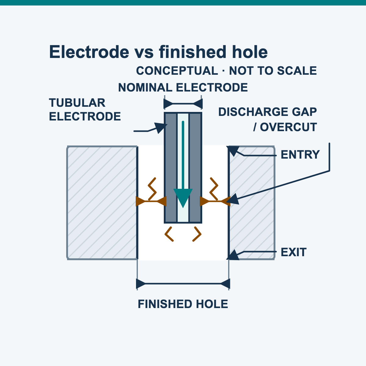
EDM drilling can create small holes in an electrically conductive workpiece by using controlled discharges around a commonly rotating tubular electrode while working fluid carries debris from the gap. But “micro-hole” is not a universal performance class. Feasibility must be decided from the required finished-hole diameter, depth, angle, material, tolerance, surface-integrity limits and inspection method—not from one nominal electrode size or a generic industry claim.
The current English HarsMarg product pages list a φ0.3–φ3.0 mm electrode-diameter range for both the D703 and DD703. This is a tooling field, not a guaranteed finished-hole range. The minimum accepted hole, practical depth, taper, straightness, position, surface condition and cycle time must be confirmed for the actual setup and drawing.
Start With the Finished-Hole Requirement
A request such as “make a 0.5 mm hole” is incomplete. The buyer and supplier should agree what will be measured, where it will be measured and how the result will be accepted. A useful drawing or RFQ defines the following fields.
| Requirement | Why It Changes Feasibility | What to State |
|---|---|---|
| Material | Standard EDM needs a sufficiently conductive path; grade, condition and coating can change the process | Exact grade, heat treatment/temper, coating, thickness and conductivity concern |
| Finished diameter | Finished-hole size is affected by discharge overcut, electrode wear and setup effects | Nominal diameter, upper/lower limits, where diameter is evaluated and any separate entry/exit limits |
| Depth and entry | Depth, surface angle and guide clearance affect electrode stability and debris removal | Hole depth or workpiece thickness, entry angle, accessible guide distance and available clearance |
| Hole type | Through holes, blind features and holes entering an internal cavity have different flushing and stop/breakthrough risks | Through, blind or cavity breakthrough; permitted bottom/exit condition; protected back wall if present |
| Geometry | Diameter alone does not define position, form, direction or taper | Datums, position, axis direction, straightness, roundness/cylindricity and taper limits as applicable |
| Surface integrity | EDM is a thermal process; a dimensional pass does not prove the wall condition is acceptable | Roughness parameter/method and any recast-layer, heat-affected-zone or microcrack limit |
| Quantity and acceptance | One successful hole does not establish repeatability or production capacity | Hole count and pattern, batch size, cycle target, sample size, inspection frequency and acceptance rule |
How EDM Drilling Forms a Small Hole
A pulse generator establishes controlled discharges across a small gap between the electrode and conductive workpiece. Each discharge removes a small amount of material. In a common EDM drilling arrangement, working fluid passes through a tubular electrode while the electrode rotates and the Z feed advances. The fluid supports dielectric recovery, cooling and removal of eroded particles.
The process avoids a conventional cutting edge and the associated cutting force, but it does not eliminate electrode wear. The electrode is consumed. Long or fine electrodes may bend, exhibit runout or vibrate; the guide, sealing, alignment and effective unsupported length matter.
Working fluid does not make the process non-thermal. Hole walls and entry/exit regions may require separate checks for recast or white layer, heat-affected material, microcracks and edge condition. The inspection depth and method should come from the part requirement rather than a general web article.
Why Electrode Diameter Is Not Finished-Hole Diameter
The nominal electrode outside diameter is only one input in the dimensional chain. Finished-hole size and shape may change with:
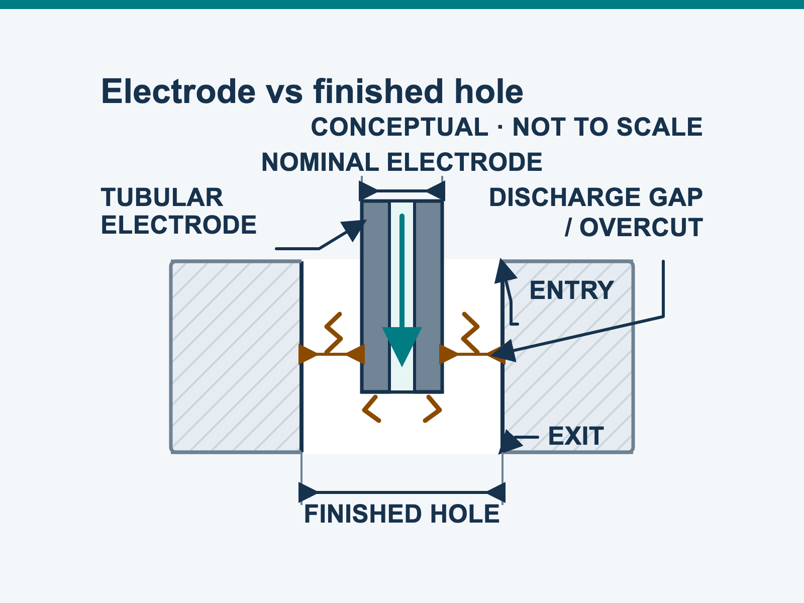
- discharge overcut: the working gap means the eroded boundary is not simply the electrode surface;
- electrode construction: material, outside/inside diameter, channel design, straightness, usable length and lot variation;
- wear and shape change: end wear, side wear or a changed tip shape can alter the result with depth and from hole to hole;
- guide and alignment: guide wear, spindle/electrode runout, concentricity and distance from the surface affect the hole axis and form;
- flushing and debris: restricted or unstable flow can produce abnormal discharge, slower progress or local variation;
- workpiece and geometry: material grade, thickness/depth, surface angle, breakthrough and internal cavities change the gap conditions;
- electrical and feed condition: use the technology guidance for the exact machine, generator, electrode and material rather than copying a fixed online recipe.
For that reason, do not approve a quotation by subtracting or adding one generic spark-gap value to the electrode catalogue field. Select and verify an electrode/process combination against the measured finished hole.
What the English D703 and DD703 Pages Establish
The HarsMarg EDM hole drilling range currently presents D703 as a non-CNC single-axis machine whose controlled feed axis is Z, and DD703 as the CNC/multi-axis option for programmed coordinate positioning. That distinction helps select the positioning workflow; it does not establish a finished-hole result.
Plan a Representative Micro-Hole Trial
Use representative material and the most demanding relevant geometry, not an easy coupon that removes the main risk. If the production part includes more than one material condition, thickness, entry angle or hole type, select a trial matrix that covers those differences.
- Freeze the acceptance requirement. Identify the drawing revision, datums, hole definition, sample quantity, measurement method and decision rule before drilling.
- Record the machine and setup. Note the exact model/configuration, guide, fixture, datum method, electrode identity and lot, usable length and alignment/runout checks.
- Record the process condition. Identify the approved machine technology/parameter revision, working fluid and condition, filtration, temperature where relevant, flushing pressure/flow as actually set, spindle/rotation and feed observations.
- Track consumable and cycle behaviour. Record holes per electrode, electrode change or dressing, wear, interruptions, abnormal discharge, breakthrough behaviour and cycle observations. Do not convert one trial time into a production guarantee before repeatability is established.
- Inspect the agreed outputs. Use calibrated or otherwise controlled equipment suited to the feature and report uncertainty or decision rules when the result is close to a limit.
- Release a documented window. Keep the accepted material, electrode/guide, setup, parameter revision, fluid condition and measurement plan together; a result is not transferable to every diameter, depth or material.
This guide is not an operating-parameter recipe. Follow the supplied machine, pulse-power, electrode, guide and working-fluid documentation. Guards/interlocks, high-pressure fluid and energized circuits require the site's approved safety and isolation procedures and qualified personnel.
Inspect More Than One Diameter
A useful acceptance report may include the following items, where the drawing requires them:
- entrance and exit diameter, plus a defined internal section or non-destructive method when depth variation matters;
- position relative to stated datums and the required coordinate pattern;
- axis direction, straightness, roundness/cylindricity and taper, each with a defined specification and method;
- entry and exit edge condition, breakthrough result and any protected back-wall condition;
- surface texture using the named parameter, direction, locations, instrument settings and number of readings;
- recast/white layer, heat-affected condition or microcracks using the agreed sectioning or other inspection method when functionally important;
- results across enough holes and electrodes to support the stated production decision.
Use the drawing's applicable standard and version. A hole that passes one diameter reading may still fail position, taper, surface integrity or repeatability. Likewise, a smooth-looking wall does not prove the dimensional or metallurgical requirement.
Frequently Asked Questions
How small a hole can D703 or DD703 make?
The current English D703 and DD703 product pages list a φ0.3–φ3.0 mm electrode range. They do not establish one unconditional minimum finished-hole diameter. Provide the material, depth, angle, finished diameter/tolerance and inspection method, then request confirmation or a representative trial.
Will a φ0.3 mm electrode produce a φ0.3 mm hole?
Not automatically. Discharge overcut, electrode construction and wear, runout, guide alignment, material, depth, flushing and process condition affect the measured hole. Select the electrode from the required finished result and verify it.
What depth-to-diameter ratio can be guaranteed?
No universal ratio is given here. Practical depth depends on the diameter, electrode/guide and usable length, material, entry condition, flushing and debris path, wear, required straightness/taper and the measurement plan. Test the deepest critical case.
Does EDM drilling produce a burr-free, heat-free hole?
Do not assume either condition. Inspect entry and exit edges against the drawing. EDM is a thermal process, so critical parts may also require recast/white-layer, heat-affected-zone or microcrack inspection.
What evidence should support a minimum finished-hole claim?
Use a condition-complete representative test: named machine/configuration, material and thickness, finished diameter and depth, entry condition, electrode and guide, fluid/flushing, parameter revision, sample size and inspection method. Report the measured result and its acceptance rule; do not turn one successful hole into a model-wide minimum.
What should a buyer send for a micro-hole review?
Send the representative material or part condition; drawing and revision; finished diameter/depth/angle; definitions for entrance, exit and any internal section; taper/straightness, position, edge and surface-integrity limits; through, blind, cavity and back-wall condition; sample size; measurement method, uncertainty and acceptance rule.
Request a Drawing-Based Review
Compare the current EDM hole drilling machines, then send the representative drawing and acceptance plan. HarsMarg can screen the D703/DD703 workflow, identify missing conditions and state which result must be confirmed by configuration review or sample drilling before a technical quotation is accepted.
Table of Contents
- Start With the Finished-Hole Requirement
- How EDM Drilling Forms a Small Hole
- Why Electrode Diameter Is Not Finished-Hole Diameter
- What the English D703 and DD703 Pages Establish
- Plan a Representative Micro-Hole Trial
- Inspect More Than One Diameter
-
Frequently Asked Questions
- How small a hole can D703 or DD703 make?
- Will a φ0.3 mm electrode produce a φ0.3 mm hole?
- What depth-to-diameter ratio can be guaranteed?
- Does EDM drilling produce a burr-free, heat-free hole?
- What evidence should support a minimum finished-hole claim?
- What should a buyer send for a micro-hole review?
- Request a Drawing-Based Review