EN
EN



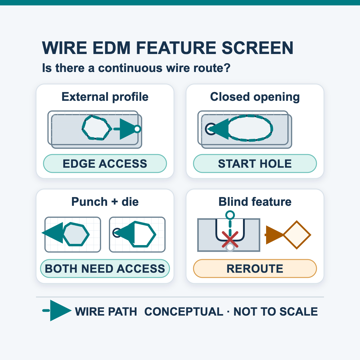
Wire EDM is a practical option for tool and die work when the required feature is a through-profile in an electrically conductive material and the wire can enter from an edge or a prepared start hole. Candidate features include punch profiles, die openings, inserts, gauges, slots and selected straight or tapered contours. The process is not the correct default for a blind cavity, a non-conductive workpiece or simple bulk removal that another method can complete more appropriately.
The purchasing decision should begin with the drawing rather than a general claim about precision. Material and heat-treatment condition, workpiece thickness, start access, datums, punch-to-die clearance, internal radius, taper or relief, surface requirement and inspection method all affect the process plan. The selected Wire EDM machine must then be checked against the work envelope, table load, cut height, taper configuration, controller and site requirements.
Which Tool and Die Features Are a Good Fit for Wire EDM?
| Feature | Why Wire EDM May Fit | What Must Be Confirmed |
|---|---|---|
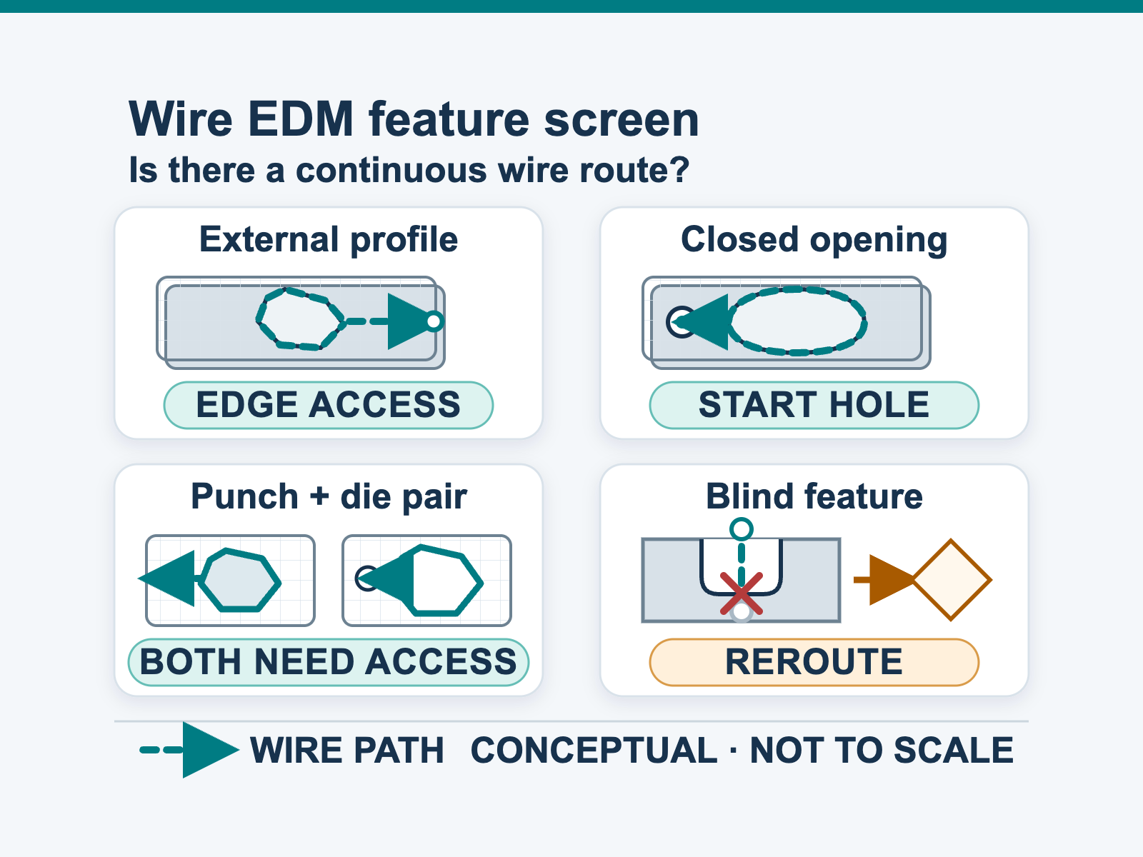
| External punch or insert profile | The wire can start from an accessible stock edge and follow a detailed through-contour. | Datum, lead-in/lead-out, slug or skeleton support, corner radii, thickness and final inspection. |
| Closed die opening or internal through-profile | The wire can be threaded through a prepared start hole and cut the enclosed profile. | Start-hole position and diameter, guide access above and below the part, flushing path and core removal. |
| Matched punch and die profiles | Related profiles can be programmed from controlled geometry. | Piercing or blanking intent, clearance per side or total clearance, material thickness, datum relationship and separate acceptance of both components. |
| Thin insert, gauge or delicate profile | Low conventional cutting load may reduce distortion caused by a rotating tool pressing into the part. | Fixture support, residual stress, cut sequence, wire behavior, flushing and movement when the profile is released. |
| Profile in a heat-treated conductive tool material | The process does not depend on a conventional cutting edge penetrating the hardened material. | Exact grade, conductivity, final condition, stock preparation, movement after material removal and surface-integrity requirement. |
| Taper, relief or different upper/lower profiles | A suitable upper/lower guide system may control a non-vertical wire path. | Angle, reference height, top and bottom geometry, direction, part thickness, guide/nozzle access and the exact model's verified taper configuration. |
| Blind mold cavity, rib or pocket | Normally not a Wire EDM feature because the wire needs a through-path. | Review die-sinking EDM or another cavity-making process. |
A fine wire does not create a mathematically sharp internal corner. The practical radius and profile depend on wire diameter, discharge gap, programmed offset, corner strategy, material, thickness and process stability. Show the required radius on the drawing rather than using “sharp corner” as the acceptance instruction.
When Is Wire EDM the Wrong Starting Process?
- Non-conductive material: conventional Wire EDM requires sufficient electrical conductivity for the intended process.
- Blind or enclosed cavity: if the wire cannot pass through the feature, review die-sinking EDM, milling or another suitable process.
- Small or deep start hole: the hole may need conventional drilling or a suitable EDM drilling machine before the wire cut.
- Simple stock removal: sawing, milling, grinding or another process may be a better route when the profile does not justify Wire EDM setup and cutting.
- Unacceptable thermal surface condition: Wire EDM can leave a recast layer and other thermal effects. Critical limits need a defined cut plan, inspection method and, when required, an approved post-process.
- Insufficient access or support: upper/lower guide clearance, flushing, workholding and safe control of the released slug must be feasible.
For a broader explanation of process benefits and limitations, read the Wire EDM advantages guide. The present page focuses on the tool-and-die workflow rather than repeating those general benefits.
A Drawing-Based Wire EDM Workflow for Tool and Die Work
- Classify the feature. Identify whether it is an external profile, internal through-opening, hole or blind cavity. This determines whether Wire EDM is a candidate at all.
- Confirm the workpiece condition. Record material grade, conductivity-relevant composition or structure, heat-treatment condition, overall size, thickness and weight. Do not assume a material name alone defines a stable recipe.
- Define the datum and wire route. Show the part orientation, profile, start edge or start hole, lead-in/lead-out, top/bottom geometry and any region where a witness or transition is not acceptable.
- Plan workholding and release. Decide how the stock, punch, insert or core will remain supported while the cut is made and when the final connection is removed. Residual stress and released weight can move the workpiece even though conventional cutting force is low.
- Select the cut strategy. Use one qualified production cut only when it can meet the drawing. Use a first cut plus trimming cuts when the final requirement and trial evidence justify that process.
- Define acceptance before cutting. State the measurement datums, locations, method and pass/fail criteria. “High precision” is not an inspection requirement.
- Approve a representative first article. Record material, stock, program revision, offset, cut stage and measured result before repeating the job.
This workflow does not guarantee that every replacement component will be identical. Repeat work still depends on the same drawing revision, stock condition, datum, fixture, wire and working-fluid condition, machine condition, process program and inspection method.
What Should the Drawing and RFQ Include?
| Information | What to State | Why It Matters |
|---|---|---|
| Geometry files | Controlled 2D drawing plus DXF/DWG or another usable profile file; 3D model when upper/lower geometry or assembly context is needed | Separates nominal geometry from the manufacturing offset and prevents an image or sample from becoming the only definition. |
| Material and stock | Grade, heat treatment/hardness or other condition, stock dimensions, thickness, weight and quantity | Supports process compatibility, capacity, fixture and trial planning. |
| Feature and access | External or internal profile, start point/hole, lead-in, cut direction if controlled, slug/core handling and available guide clearance | Confirms that the wire, guides and flushing can reach the complete feature. |
| Tool relationship | Punch/die function, blanking or piercing intent, clearance per side or total, strip/material thickness, land and relief requirements | Prevents the punch and die from being programmed as an undefined pair. |
| Dimensional acceptance | Datums, size/profile/position tolerance, straightness or perpendicularity, taper/angle, corner radius and required measurement locations/method | Turns “accuracy” into verifiable drawing fields. |
| Surface acceptance | Ra/Rz or other stated parameter, measurement location/direction, edge/witness requirement, and any recast-layer or microcrack limit | Determines whether a trimming or post-process plan and additional inspection are needed. |
| Machine and site | Required travel/load/cut height, taper or axis need, controller/file needs, destination country, power supply and planned automation interface | Connects the job requirement to the quoted machine and installation. |
Single-Cut or Multi-Cut for Tool and Die Work?
HarsMarg's current single-cut and multi-cut Wire EDM machines use reusable molybdenum wire stored on a wire drum and moving back and forth through the cutting zone. The selection difference is the planned cut sequence, not an automatic promise that one family is correct for every tool.
| Decision Point | Single-Cut | Multi-Cut |
|---|---|---|
| Process plan | One qualified production cut | A first cut followed by one or more controlled trimming cuts when required |
| When to evaluate | When a representative first article shows that one cut can meet the drawing and surface requirement | When the acceptance target justifies additional allowance, offset control and inspection after trimming |
| Tool/die questions | Can the required clearance, profile, taper/squareness, radius and finish be accepted after the one planned cut? | Which result belongs to the first cut, which belongs to the final trim, and how will each critical field be measured? |
| Quotation comparison | Include setup, start-hole work if needed, full cut, slug handling and inspection | Include setup, first cut, every trimming pass, inspection and any approved post-process |
Do not compare the two families by transferring a result from one material, specimen or model to another tool. For a fuller explanation of the architecture and cut-sequence terminology, see single-cut versus multi-cut Wire EDM.
Define the Acceptance Plan Before the Sample Cut
A sample is useful only when it represents the purchasing decision. Use the intended material and condition, a relevant thickness, the same type of profile or corner, the planned cut sequence and the agreed measurement method. Record the model/configuration, wire, working-fluid condition, program revision, offset and cut stage with the result.
For a tool-and-die sample, agree at least:
- which dimensions, profiles and datum relationships are critical;
- whether clearance is checked on the punch, die or assembled pair;
- where taper, straightness, perpendicularity and corner radius are measured;
- which surface parameter, location and direction are used;
- whether entry/exit, lead-in, slug separation and edge condition are acceptable;
- whether surface-integrity testing or a post-process is required;
- what constitutes approval before repeat production or machine acceptance.
This makes the sample a verifiable acceptance step rather than a demonstration chosen only because it is easy to cut.
Frequently Asked Questions
Can Wire EDM machine a blind mold cavity?
Normally no. The wire needs a through-path between the upper and lower guides. A blind three-dimensional cavity is usually reviewed for die-sinking EDM, milling or another cavity-making process.
Does hardened tool steel automatically make Wire EDM the best choice?
No. A hardened conductive material can be a candidate because the process does not rely on a conventional cutting edge, but geometry, conductivity, stock condition, tolerance, surface integrity, access and total process route still decide whether Wire EDM fits.
Does a closed die opening always need a start hole?
A closed internal wire-cut profile normally needs a suitable start hole unless the workpiece or process provides another verified threading route. The start hole must be positioned so that the lead-in, finished profile and slug plan remain acceptable.
Can the same contour be used for both the punch and die?
Do not assume so. The drawing should state the blanking or piercing function, material thickness, required clearance and datum relationship. The punch and die profiles, offsets and acceptance criteria should be controlled separately.
How should a buyer choose between single-cut and multi-cut?
Use the drawing and a representative trial. Select one planned cut only when it meets the agreed result. Evaluate trimming cuts when the final dimensional or surface requirement justifies the extra controlled process. Do not choose from a generic accuracy or roughness claim.
Request a Tool-and-Die Wire EDM Review
Send the controlled drawing/profile file, material and condition, stock dimensions and weight, thickness, start-hole or edge access, datums, punch/die clearance, taper or relief, corner radius, surface/integrity requirement, inspection method, quantity, destination country and power supply. HarsMarg can then compare the job with the current machine range and identify which points require a representative test.
Request a drawing-based technical review. Final capability, configuration and acceptance terms should be stated in the model-specific quotation rather than inferred from this general guide.
Table of Contents
- Which Tool and Die Features Are a Good Fit for Wire EDM?
- When Is Wire EDM the Wrong Starting Process?
- A Drawing-Based Wire EDM Workflow for Tool and Die Work
- What Should the Drawing and RFQ Include?
- Single-Cut or Multi-Cut for Tool and Die Work?
- Define the Acceptance Plan Before the Sample Cut
- Frequently Asked Questions
- Request a Tool-and-Die Wire EDM Review