EN
EN



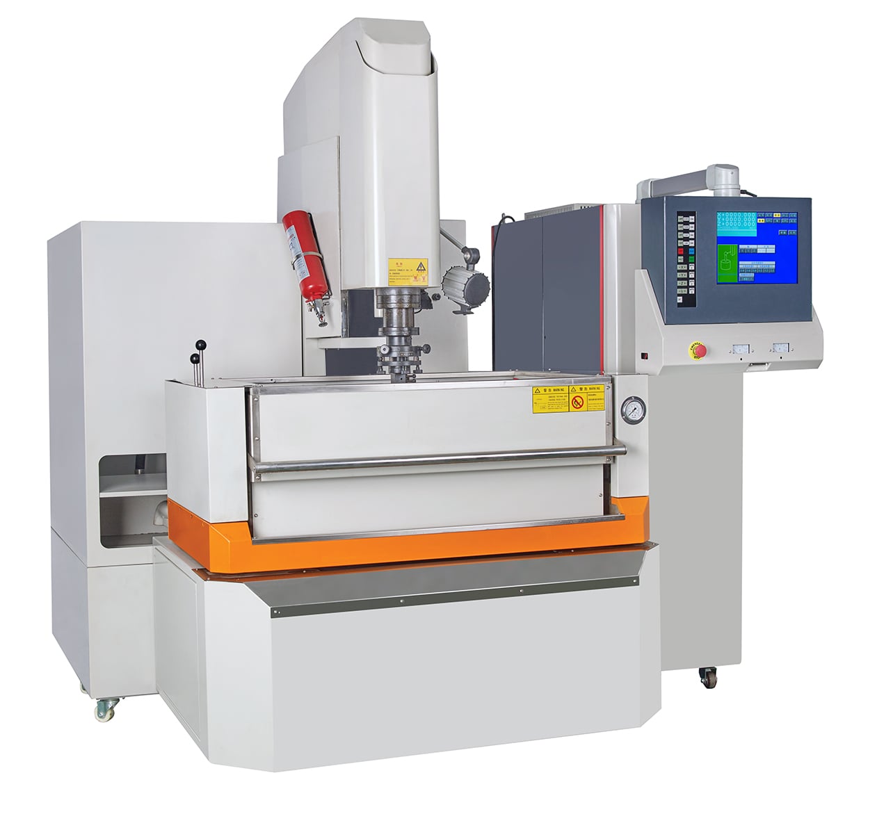
Sinker EDM machines form cavities in electrically conductive workpieces using a shaped electrode and controlled electrical discharges. For a mold cavity, useful accuracy starts with a defined drawing, a feasible electrode approach and an inspection plan. A machine-category description alone cannot establish the tolerance of the finished cavity.
When reviewing the available products, separate machine travel and positioning specifications from the dimensions and surface condition required on your mold. The electrode, discharge gap, material, machining sequence and measurement conditions all need consideration before a result can be accepted.
Use the following planning steps to prepare a mold-cavity inquiry. They cover electrode access, gap allowance, flushing, wear, references and acceptance. They do not prescribe a universal tolerance, roughness value, cavity-depth ratio or cutting recipe.
Plan the Mold Cavity Before Selecting a Machine
Define the Feature and Its Acceptance Requirements
Identify the cavity surfaces, ribs, slots, corners and depths that must be produced. Mark the dimensions and datums that control fit or function. Distinguish a blind cavity from a through feature and explain which surfaces are accessible for machining and inspection.
Check whether sinker EDM is the appropriate process for each feature rather than assigning the entire mold to one method. A shaped electrode needs a practical approach and withdrawal path. Do not assume it can reach every enclosed passage or undercut merely because EDM does not use a rotating cutter.
State dimensional tolerance, surface roughness and any surface-integrity requirement separately. Identify whether acceptance applies immediately after EDM or after polishing, coating or another operation. This prevents a satisfactory roughness reading from being mistaken for complete cavity acceptance.
Confirm the Machine and Electrode Approach
For the sinker EDM machines under consideration, confirm the exact model, controller, generator and supplied configuration. Ask how the proposed electrode will be positioned and fed. Do not infer a CNC function, rotary axis or automatic electrode changer from the equipment category.
Check the workpiece, fixture, electrode and holder together against the available working space and stroke. Include loading access, safe withdrawal and the required dielectric arrangement. Nominal axis travel alone does not establish that the complete setup fits.
List any requested orbiting, probing, electrode changing, temperature control or unattended-operation features separately. Have the supplier identify what is included, optional or unavailable on the offered machine. Keep those configuration decisions separate from finished-part acceptance.
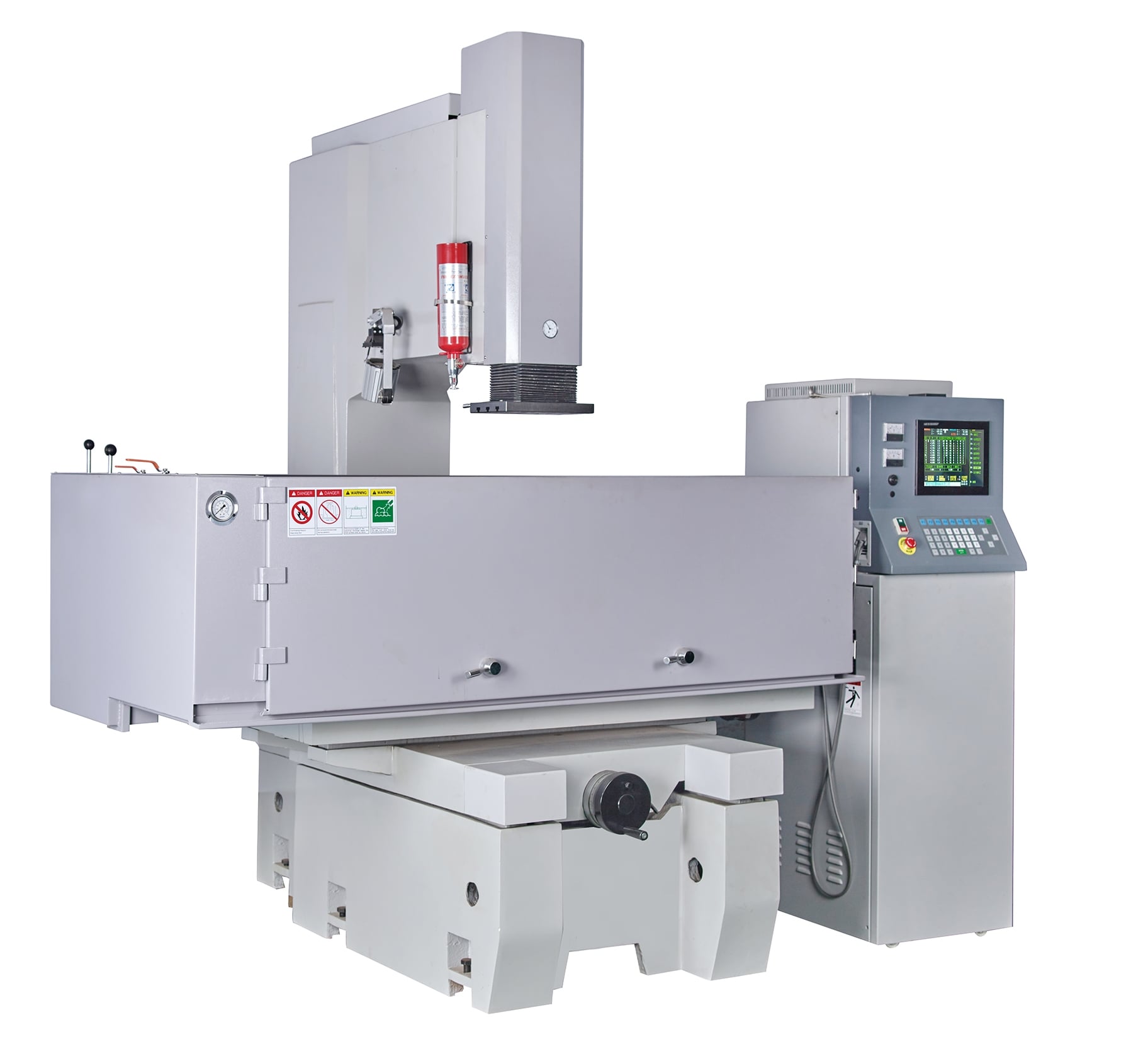
Design the Electrode Around the Required Cavity
Allow for the Discharge Gap
The electrode and workpiece operate across a discharge gap, so the electrode is not simply a dimension-for-dimension copy of the desired cavity. Prepare its dimensions and allowances for the proposed machining conditions. Confirm how the gap is considered on the sidewalls, bottom and critical details.
Discuss roughing and finishing conditions before finalizing the electrode drawing. Their allowances may differ. Ask which dimensions the electrode manufacturer must supply and which adjustments the offered machine can perform; do not use a gap value copied from an unrelated machine or material.
Review small radii, thin electrode sections and sharp details individually. Identify how they will be manufactured, checked and maintained during machining. A sharp feature in the CAD model is not, by itself, proof of a producible or acceptable cavity feature.
Provide Access and a Debris Escape Path
Show any pre-machined pocket and the material remaining for EDM. Define the stock boundary rather than assuming that machining the whole cavity from solid is always preferable. Agree which operations belong in the proposed sequence before comparing quotations.
For a deep or narrow cavity, review electrode access and the path by which fluid and debris can leave the gap. Ask for a feasible flushing and withdrawal strategy for the actual geometry. Do not replace that review with a universal depth-to-width claim.
Treat cooling passages as a separate geometry question. Provide the required route, openings and intersections, then ask whether an electrode can approach and withdraw while allowing debris removal. An arbitrary enclosed conformal channel must not be assumed feasible on a standard sinker setup.
Plan Roughing and Finishing Stages
Choose Electrodes for Each Stage
Identify the proposed electrode material and grade, not just the description “copper” or “graphite.” For a graphite electrode, review the manufacturer's application-specific grades. Discuss the fine details, engaged area, machining stage and electrode-manufacturing method with the supplier. Select material for the actual job rather than promising the same finish from every electrode grade.
Ask whether roughing and finishing use the same electrode, separate electrodes or replacement electrodes. Include the required quantity and inspection of those electrodes in the plan. Do not assume that one electrode will retain every critical detail for the full job.
Consider the area engaged in the cavity as well as its depth. A small accessible feature and a broad cavity face can present different debris-removal conditions. Qualify the proposed setup with representative geometry instead of transferring a result from a convenient small sample.
Control Electrode Wear and Preserve References
Sinker EDM is not a zero-electrode-wear process. Changes to the electrode tip, edges or other critical surfaces need to be considered in the machining plan. Ask how electrode condition will be checked and when an electrode will be replaced or a permitted adjustment made.
Define the workpiece datum and the electrode-holder references before the first operation. Record how they will be maintained when electrodes or setups change. Inspect the relevant references rather than assuming that repeated cavities will be identical because they use the same program.
Where an orbiting or compensation method is proposed, confirm its availability and practical use on the offered controller. Describe the intended movement and dimensional allowance. Do not treat a catalog function as automatic correction of every wear or setup error.
Match Material and Dielectric to the Setup
Identify the Workpiece and Heat Treatment
Electrical conductivity is a basic requirement for conventional sinker EDM. Hardened material can be a suitable application, but hardness alone does not determine the machining result. Specify the actual material and condition rather than assuming equal machining behavior across all conductive alloys.
Provide the material grade, heat-treatment condition and relevant coating or prior processing. If several materials are under consideration, ask for a separate assessment of each. A successful cavity in one tool steel does not qualify every carbide or alloy for the same settings and result.
Agree where EDM belongs in the complete manufacturing route. Identify any later heat treatment, polishing or coating that may affect acceptance. Do not describe sinker EDM as automatically eliminating these operations or the dimensional checks associated with them.
Specify Flushing and Surface Integrity
Use the dielectric and fluid-management procedure specified for the actual machine. Confirm the required fluid, filtration, level and maintenance conditions. Do not assume that fluids or additive systems described for another process are interchangeable with the supplied setup.
Review the proposed flushing, electrode withdrawal and debris-removal arrangement with the cavity geometry. Follow the machine's documented procedure for adjustments. If machining becomes unstable, investigate the setup and fluid conditions rather than assuming that automatic control will resolve every problem.
EDM can leave thermally affected material at the machined surface. If the drawing specifies recast-layer, crack or other surface-integrity limits, agree a separate examination method. Do not claim that a fine roughness reading proves there is no thermal effect or establishes mold service life.
Verify the Cavity Against the Drawing
Plan Instruments and Measurement Access
Select measurement methods for the actual dimensions, datums and surfaces. Keep axis-positioning specifications separate from the finished cavity result. Discharge allowance, electrode condition and setup references still need assessment against the drawing.
Check whether the proposed instrument can reach the bottom, sidewalls and narrow features that require inspection. Identify any feature needing a different agreed method. Do not assume that a probe, optical system or on-machine measurement function is fitted or can inspect every internal surface.
Mark measurement locations and define the relevant instrument, calibration, datum alignment and environmental conditions. For roughness, state the parameter, units and measurement method. Compare results obtained under compatible conditions, not photographs or isolated numbers without their context.
Accept the Full Machining Sequence
Choose a representative trial that includes the critical cavity depth, detail, engaged area and access conditions. Identify the machine configuration, electrode and workpiece in its record. A trial on a different, easier shape should not stand as proof for all mold features.
Inspect the result after the agreed roughing and finishing sequence. If polishing or another operation follows, define which checks must be repeated afterwards. Removal of surface material must not be assumed to leave every edge and dimension unchanged.
Keep the acceptance record tied to the drawing revision and specified features. Record the measured result, measurement locations and any agreed remaining work. Treat dimensional, roughness and surface-integrity requirements as separate checks, not as a single claim of “high accuracy.”
Prepare a Mold Cavity Inquiry
Provide the Drawing and Electrode Plan
Submit the drawing revision, units, material and condition, overall workpiece dimensions and critical cavity details. Include datums, required tolerances, roughness and any specified surface-integrity limits. Explain which features need technical review rather than sending only a general request for a mold machine.
If electrodes already exist, provide their drawings, material, inspection status and holder arrangement. Otherwise, identify who will design and manufacture them. Ask for the proposed roughing and finishing plan before treating electrode quantity or replacement needs as settled.
Include workpiece weight, available factory power, destination country and requested production quantity. State any handling, automation or interface requirement separately. These inputs support configuration review without implying that every option or delivery arrangement is included.
Compare the Complete Job Rather Than a Best Case
Compare the same scope of work: electrode manufacture and inspection, setup, machining stages, electrode changes, finishing and final inspection. A discharge-rate or machining-time claim alone is not the duration or cost of the complete accepted job.
Require the quotation to identify the proposed machine and the functions needed for this cavity. If a production case or sample result is offered, review its geometry, material, electrode sequence and acceptance conditions. Do not apply its cycle time, labor needs or savings to a different mold without a corresponding assessment.
For a technical review, send the complete inquiry information with the features and acceptance requirements you want assessed. Ask which setup and trial conditions can be proposed, and which points remain to be confirmed. Agree those conditions before accepting a performance commitment.
FAQ
What Accuracy Should Be Specified for a Mold Cavity?
Specify the tolerance of each relevant dimension or geometric feature on the drawing, together with datums and the inspection method. State roughness and any surface-integrity requirement separately. There is no universal tolerance that qualifies every machine, electrode, cavity and material.
Can Sinker EDM Make Any Cooling Channel?
No general capability should be assumed. The proposed electrode needs an approach, withdrawal and debris-removal path for the required geometry. Review enclosed, curved and intersecting passages individually; a conventional sinker setup is not a blanket solution for arbitrary conformal channels.
Is Machining Independent of Material Hardness?
Conventional sinker EDM can be considered for electrically conductive hardened workpieces, but this does not mean that every material gives the same machining behavior. Identify the actual grade and condition, then assess the electrode, settings and finished result for that combination.
How Does Electrode Wear Affect the Cavity?
Wear can change the electrode geometry used to form the cavity. Include electrode checks, replacement needs, permitted adjustments and reference preservation in the roughing and finishing plan. Confirm the available controller functions and inspect the finished cavity rather than assuming wear is automatically eliminated.