EN
EN



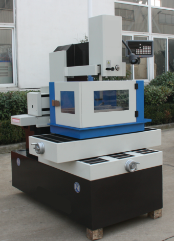
Wire EDM accuracy improves when the drawing requirement, machine condition, setup, cutting sequence and inspection method are controlled as one process. There is no universal parameter that can correct an unclear datum, unstable fixture, unsuitable wire condition, wrong offset or inconsistent measurement method. Define the required result first, then control and record the variables that can influence it.
This guide refers specifically to HarsMarg's current single-cut and multi-cut Wire EDM machines. Both families use reusable molybdenum wire stored on a wire drum and moving back and forth through the cutting zone. Settings or consumables published for a different wire-transport architecture should not be copied to this reciprocating-wire system unless the selected HarsMarg model and its documentation explicitly support them.
What Does “Wire EDM Accuracy” Mean?
Before improving accuracy, identify which result is actually being discussed. The word “precision” alone is not an acceptance criterion.
| Term | What It Describes | What It Does Not Prove |
|---|---|---|
| Positioning accuracy | The difference between a commanded machine-axis position and the measured position under a stated test | The tolerance of every cut part |
| Repeat positioning | How consistently an axis returns to a commanded position under the specified test method | Finished-part repeatability across different materials and setups |
| Machining or cutting accuracy | The measured deviation of a cut feature or test piece from its specified value under stated conditions | A series-wide guarantee without the test piece and process conditions |
| Geometric result | Feature form such as straightness, parallelism, squareness, taper, profile or corner condition | Surface roughness or axis positioning performance |
| Surface roughness | A measured surface parameter, such as Ra, using a stated method | Dimensional accuracy |
| Command increment or pulse equivalent | The smallest programmed or displayed movement increment | Actual positioning or machining accuracy |
ISO 14137:2015 likewise treats geometric tests, positioning accuracy and repeatability, machining tests and circular tests as different checks for Wire EDM machines. A formal machine test does not replace inspection of the customer's finished part, and this article does not claim that every HarsMarg model has been tested or certified to one international standard.
Wire EDM Accuracy Control Checklist
Use the following sequence before releasing a new or critical job. The exact settings must come from the selected machine's manual, controller documentation and an approved process sheet.
| Control Point | What to Confirm | What to Record |
|---|---|---|
| 1. Drawing and acceptance | Current revision, units, datums, feature tolerance, profile, taper, corner and surface requirement | Drawing revision and agreed inspection rule |
| 2. Workpiece | Material grade, hardness when relevant, dimensions, thickness, weight, stock condition and any heat treatment | Material and blank identification |
| 3. Machine fit | X/Y travel, worktable, table load, maximum allowable workpiece thickness, taper requirement and controller capability for the quoted model | Machine model and configuration |
| 4. Fixture and datum | Clean seating, stable support, controlled clamp force, reliable electrical connection, cutting clearance and verified datum | Fixture reference, clamp locations and zero-setting method |
| 5. Molybdenum wire | Approved diameter and specification, usable condition, correct drum winding, guide path, travel margin and qualified tension/transport settings | Wire specification, condition and process-sheet reference |
| 6. Working fluid and flushing | Approved fluid, suitable level and condition, filtration or maintenance status, circulation and stable delivery to the cutting gap | Fluid product, condition and flushing arrangement |
| 7. Program and offset | Program revision, units, origin, contour direction, start point, lead-in/out, taper, wire offset and cutting clearance | Program and parameter-set revision |
| 8. Cutting sequence | One planned production cut for single-cut work, or a defined first cut plus trimming sequence and allowances for multi-cut work | Cut count, allowance and offset for each pass |
| 9. Process stability | Normal wire travel, discharge, fluid delivery and machine condition during the trial or first part | Observed abnormal condition and each corrective change |
| 10. Inspection and release | Defined datums, measuring method, locations, environment and acceptance decision | As-cut results, corrections and production approval |
For a detailed preparation sequence, also see the Wire EDM setup checklist.
1. Define the Required Result Before Adjusting the Process
Start from the latest approved drawing and separate each requirement. A size tolerance, profile tolerance, taper, corner radius and surface-roughness target are not interchangeable. Confirm the datum system, measurement locations and acceptance method before the first cut. If the drawing or inspection rule is unclear, do not try to solve the uncertainty by choosing a more aggressive machine setting.
For a critical part, agree whether the supplier is evaluating the machine, a representative test piece or the customer's actual component. These are different tasks. A machine-positioning test does not automatically establish the tolerance of a complex part, while one successful sample does not by itself establish long-run process capability.
2. Match the Complete Setup to the Selected Machine
Check the workpiece and fixture together against the model's X/Y travel, worktable dimensions, table-load limit and allowable workpiece thickness. Include clamps, supports, guide clearance and any U/V movement needed for taper. A large travel figure alone does not prove that a machine can carry a heavier or thicker setup.
Confirm that the machine is in the maintenance and verification state required by its manual and the site's quality system. Inspect accessible wire-path components, fluid delivery points, the table area and the fixture for contamination, damage or obstruction. Axis compensation, machine geometry and generator calibration are service or metrology tasks, not normal operator adjustments.
3. Control Fixturing, Support and Electrical Contact
Clean the workpiece, supports and locating surfaces. Remove loose burrs, chips, rust or contamination that could change seating, weaken the electrical connection or shift the datum. Support the part so that it does not rock, sag or move when the wire reverses or fluid flows through the cutting zone.
Use enough clamp force to prevent movement without distorting a thin, long or stress-sensitive workpiece. Keep clamps outside the programmed path and allow clearance for the guides, nozzles and taper movement. Stable workholding matters because vibration, overhang and flushing forces can affect the result even though Wire EDM does not use a conventional cutting force at a tool edge.
4. Control the Molybdenum Wire, Drum and Guide Path
Use the molybdenum-wire diameter and specification approved for the selected model and job. Inspect the exposed wire for contamination, kinks, flattening, abnormal wear or other damage. Check that the wire is wound correctly on the drum, has adequate travel margin and follows the documented route through the rollers, guides and cutting zone.
Set wire tension and transport from the qualified process for that machine, wire and cutting sequence. Use only the wire-handling functions documented for the quoted model and controller. The wire remains flexible under tension, so wire deflection or lag can contribute to straightness, corner and taper error, especially when the workpiece, flushing or parameter condition changes.
5. Maintain Stable Working-Fluid and Flushing Conditions
Use the working fluid approved for the selected reciprocating-wire machine. Check its level, visible condition, circulation, filtration and any concentration or control value specified by the machine and fluid instructions. No universal conductivity, concentration or replacement interval is stated for the complete HarsMarg range.
Deliver enough fluid to support stable discharge and debris removal without using a flow arrangement that pushes the wire away from its intended path. The suitable arrangement depends on part thickness, contour, fixture obstruction and whether the cut is open or poorly flushed. Record the arrangement used for an approved sample so it can be reproduced.
6. Verify the Program, Offset and Cutting Sequence
Before cutting, check the program revision, units, coordinate orientation, start point, contour direction, lead-in/out, taper command and wire offset. Confirm that the selected parameter set was qualified for the material, thickness, molybdenum wire and required result. A general statement such as “lower energy always gives higher accuracy” is not a substitute for a validated condition.
Single-Cut Process
For a single-cut Wire EDM job, the one planned production cut must meet the agreed drawing and finish requirement. Inspect the controlled first piece before releasing the batch. Do not assume that one offset or parameter set transfers unchanged to another material, thickness or contour.
Multi-Cut Process
For a multi-cut Wire EDM job, plan the first-cut allowance and the offset and qualified condition for every trimming pass. Trimming can improve dimensional and surface results when the wire, fluid, electrical parameters, tension, flushing, workholding and allowance are correctly matched. It does not guarantee one accuracy value for every part.
See Fast vs Medium-Speed Wire EDM: Single-Cut vs Multi-Cut for the current HarsMarg category distinction and selection logic.
For definitions of cut-area rate, active cutting time and accepted-part cycle time, see the Wire EDM cutting-speed optimization guide.
7. Control Temperature and Other Environmental Influences
When a job has a tight dimensional requirement, keep the machine, workpiece, fixture and measuring equipment in stable conditions appropriate to the agreed process and inspection plan. Avoid exposing the setup to an abrupt temperature change, direct airflow, direct sunlight or an external vibration source that could make machining or measurement inconsistent.
No single room-temperature tolerance or stabilization time is prescribed here. Use the selected machine's installation and operating instructions, the workpiece material, the required tolerance and the customer's measurement rule. Record the relevant condition when comparing trial cuts made at different times.
8. Use a Controlled Trial and Change One Variable at a Time
For a new material, thickness, fixture, contour or critical tolerance, make a representative sample or controlled first part. Record the baseline program, offset, cutting sequence, wire, fluid arrangement and parameter-set reference. If the result is outside the requirement, identify the likely cause and change one controlled variable at a time rather than making several undocumented adjustments.
During the cut, watch for abnormal wire travel, repeated wire breaks, unstable discharge, inconsistent flushing, vibration or a sudden change in the process. Stop and investigate according to the machine procedure when the cause is unknown. Do not rely on an unverified automatic recovery function to protect accuracy.
How Should a Wire EDM Part Be Measured?
The measuring method must match the feature and tolerance. A micrometer, gauge, optical system, CMM, surface-roughness instrument or another method may be appropriate, but no one instrument is required for every part. Use equipment with suitable capability and current calibration status under the site's quality procedure.
| Result to Verify | Measurement Plan | Record Needed |
|---|---|---|
| Feature size or profile | Use the drawing datum and specified feature definition; measure at the required locations with a suitable method | Nominal value, measured value, location and instrument/method |
| Straightness or top-to-bottom deviation | Define the height and sections to be checked; include upper, middle or lower locations when the drawing or test plan requires them | Section locations and individual results |
| Taper or angle | Measure the specified geometry and relevant upper/lower sections; do not infer taper accuracy from U/V travel alone | Nominal angle or dimensions, measured values and datum |
| Corner or contour condition | Check the locations identified on the drawing, including the required corner radius or profile zone | Inspection locations and deviations |
| Surface roughness | State the parameter, measurement direction, sampling or evaluation procedure and acceptance limit | Parameter such as Ra, method and measured result |
| Repeatability or capability | Use an agreed sample size and the same controlled setup and measurement method; do not infer a production trend from one part | Individual results, sequence, changes and analysis rule |
If the result is close to the acceptance limit, confirm that the measurement method, instrument capability, datum and environmental condition are suitable before changing the machining process. Record the as-cut result as well as any offset correction so the final process can be repeated.
How HarsMarg States Model-Specific Performance
The current published HarsMarg single-cut product pages state an optimal machined surface-roughness reference of Ra ≤ 2.0 µm, subject to the stated process conditions. The DK7725 page also gives a conditioned machining-accuracy reference of ≤ 0.015 mm for a Cr12, 10 mm-thick octagonal test piece. That example must not be copied to every single-cut model or treated as a guarantee for another workpiece.
The current multi-cut pages state Ra ≤ 2.0 µm after the first cut and Ra ≤ 0.8 µm after trimming cuts. They also describe a specified 40 mm-high, 28 mm regular octagonal test piece with dimensional deviation of 0.009 mm across the vertical section and 0.010 mm across the horizontal section after trimming.
These single-cut and multi-cut references use different test pieces and conditions, so they are not a controlled head-to-head comparison. For a critical requirement, the quotation should identify the selected model and configuration and, where appropriate, an agreed sample-cut and inspection plan.
Troubleshooting Dimensional or Surface Variation
The items below are possible contributors, not automatic diagnoses. Preserve the baseline, investigate safely and avoid changing several settings at once.
| Observed Result | Possible Contributors | First Checks |
|---|---|---|
| Overall size shift | Wrong program revision, units, datum, offset, wire condition or measurement setup | Recheck the drawing, program, zero, offset and inspection method before changing electrical parameters |
| Top-to-bottom size or taper difference | Wire path or guide condition, taper program, tension/transport setting, flushing, wire deflection or workpiece thickness | Inspect the documented setup and compare measurements at defined sections; refer service checks to qualified personnel |
| Bowed or poor straightness result | Wire lag or deflection, unstable flushing, unsuitable qualified condition, overhang, vibration or workpiece movement | Check support, clamping, wire path, fluid delivery and process stability |
| Corner or contour error | Program geometry, offset, lead-in/out, corner strategy, wire behavior or unsuitable condition for the geometry | Verify the drawing and toolpath first, then compare with the controller and model documentation |
| Surface roughness outside target | Wrong cut sequence, trimming allowance or condition, unstable discharge, fluid condition, wire/guide condition or inconsistent measurement | Confirm whether the result is from the first cut or final trim and review the approved process and roughness method |
| Repeated wire breakage | Damaged or unsuitable wire, incorrect path or winding, tension/transport setting, poor flushing, unstable electrical condition or obstruction | Stop, inspect the wire system and process condition, and correct the cause before resuming |
When Should Machine Accuracy Be Verified?
There is no verified six-month calibration rule for every HarsMarg installation. Follow the selected model's maintenance instructions and the user's quality system. Verification may also be appropriate after a collision, relocation, relevant repair or component change, an unexplained dimensional trend, or before a formal acceptance test when the purchase agreement requires it.
Formal machine-geometry, positioning and repeatability checks should be planned and performed by qualified personnel using the applicable procedure and suitable measuring equipment. Do not change protected compensation values merely because one part measures outside tolerance; first separate programming, setup, process and measurement causes from an actual machine condition.
Information to Send for an Accuracy-Critical Inquiry
For a useful model and process review, provide:
- The current drawing, units, datums and inspection standard
- Material grade and hardness or heat treatment when relevant
- Maximum X/Y dimensions, thickness, weight and fixture information
- Critical feature tolerances, profile, taper, corner radius and surface-roughness target
- Required single-cut or multi-cut process, if already specified
- Quantity, batch size and cycle-time objective
- Required sample-cut, measurement record or acceptance report
- Local voltage and frequency, installation location and destination country
- Any required controller, automation or communication function
Review the complete Wire EDM machine range, compare the single-cut models and multi-cut models, or send the job information to HarsMarg. Final capacity, configuration and expected result should be confirmed for the quoted model and, when necessary, through an agreed sample-cut and inspection plan.
Frequently Asked Questions
Is positioning accuracy the same as finished-part accuracy?
No. Positioning accuracy describes machine-axis behavior under a stated test. Finished-part accuracy also depends on the program, datum, fixture, molybdenum wire, working fluid, flushing, electrical condition, cutting sequence, material, thickness and inspection method.
Does multi-cut Wire EDM automatically guarantee a tighter tolerance?
No. Trimming cuts provide a process route for improving the result, but the outcome remains conditional on the selected model, controller, workpiece, wire, allowance, parameter sets, fixture and measurement method.
Which wire does the current HarsMarg range use?
The current HarsMarg single-cut and multi-cut ranges described here use drum-stored, reciprocating molybdenum wire. Use only the wire specification approved for the selected model and job; do not import a consumable recommendation from a different Wire EDM architecture.
How often should a Wire EDM machine be calibrated?
No universal interval is stated for the full HarsMarg range. Follow the model manual, maintenance plan and site quality system, and consider qualified verification after relevant service events or when measured trends indicate a possible machine condition.
Can an operator correct an accuracy problem by changing axis compensation?
Not as a normal job adjustment. First verify the drawing, program, datum, fixture, wire, fluid, process and measurement method. Machine geometry, positioning verification and protected compensation changes should be handled by authorized, qualified personnel.
Next Step
Send HarsMarg the drawing, material, workpiece dimensions and weight, target tolerance and roughness, quantity, local power supply and required inspection method. The technical review can then identify a suitable model range and the conditions that should be confirmed in the quotation or sample-cut plan.
Table of Contents
- What Does “Wire EDM Accuracy” Mean?
- Wire EDM Accuracy Control Checklist
- 1. Define the Required Result Before Adjusting the Process
- 2. Match the Complete Setup to the Selected Machine
- 3. Control Fixturing, Support and Electrical Contact
- 4. Control the Molybdenum Wire, Drum and Guide Path
- 5. Maintain Stable Working-Fluid and Flushing Conditions
- 6. Verify the Program, Offset and Cutting Sequence
- 7. Control Temperature and Other Environmental Influences
- 8. Use a Controlled Trial and Change One Variable at a Time
- How Should a Wire EDM Part Be Measured?
- How HarsMarg States Model-Specific Performance
- Troubleshooting Dimensional or Surface Variation
- When Should Machine Accuracy Be Verified?
- Information to Send for an Accuracy-Critical Inquiry
-
Frequently Asked Questions
- Is positioning accuracy the same as finished-part accuracy?
- Does multi-cut Wire EDM automatically guarantee a tighter tolerance?
- Which wire does the current HarsMarg range use?
- How often should a Wire EDM machine be calibrated?
- Can an operator correct an accuracy problem by changing axis compensation?
- Next Step