EN
EN



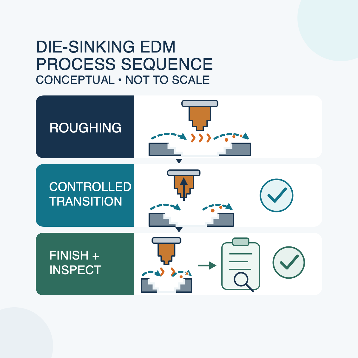
To improve sinker EDM surface finish, use a staged roughing-to-finishing process, progressively reduce discharge energy, keep the electrode and spark gap stable, remove debris consistently, control thermal variation and verify the result with an agreed measurement method. No single current, pulse or voltage setting is correct for every machine, electrode, workpiece or cavity.
Start with the technology or condition table supplied for the exact machine and generator. Then qualify the process on representative material and geometry before using it on a production part. Record each controlled change so that a smoother result can be reproduced rather than achieved once by trial and error.
Surface Finish and Surface Integrity Are Not the Same
Sinker EDM removes electrically conductive material through controlled electrical discharges between a shaped electrode and the workpiece. Each discharge creates a small crater. Roughing conditions normally prioritise material-removal rate, while finishing conditions use lower-energy discharges to create smaller overlapping craters. The final texture also depends on electrode condition, debris in the gap, cavity geometry, flushing, servo behaviour and thermal stability.
Surface finish describes the measured topography, commonly reported with parameters such as Ra or Rz. Surface integrity concerns the condition below and at the surface, which may include the recast or white layer, heat-affected material and microcracking. A low Ra value does not prove that a critical part has an acceptable recast layer or is free from microcracks.
Keep dimensional accuracy separate as well. A cavity can meet a roughness target and still fail size, taper, corner, radius or form requirements. If fatigue, sealing, coating adhesion, corrosion performance, medical use or another critical function is involved, the drawing and quality plan should state the required surface-integrity inspection rather than relying on roughness alone.
Define the Acceptance Method Before Changing Settings
Before adjusting the burn, confirm what the drawing or customer actually requires:
- workpiece material, grade, hardness or heat-treatment condition;
- cavity depth, projected or engaged area, ribs, corners, venting and debris escape path;
- required dimensions, tolerances, radii and edge condition;
- required Ra, Rz or other texture parameter, including the applicable standard and measurement method;
- measurement direction, locations, instrument settings and number of readings;
- any recast-layer, microcrack, metallography or other surface-integrity limit;
- whether later polishing, coating or another process will change the surface or dimensions.
Without this baseline, “better finish” is ambiguous. A visually brighter surface, a lower Ra reading and an acceptable functional surface are related but not interchangeable outcomes.
Use a Controlled Roughing-to-Finishing Sequence
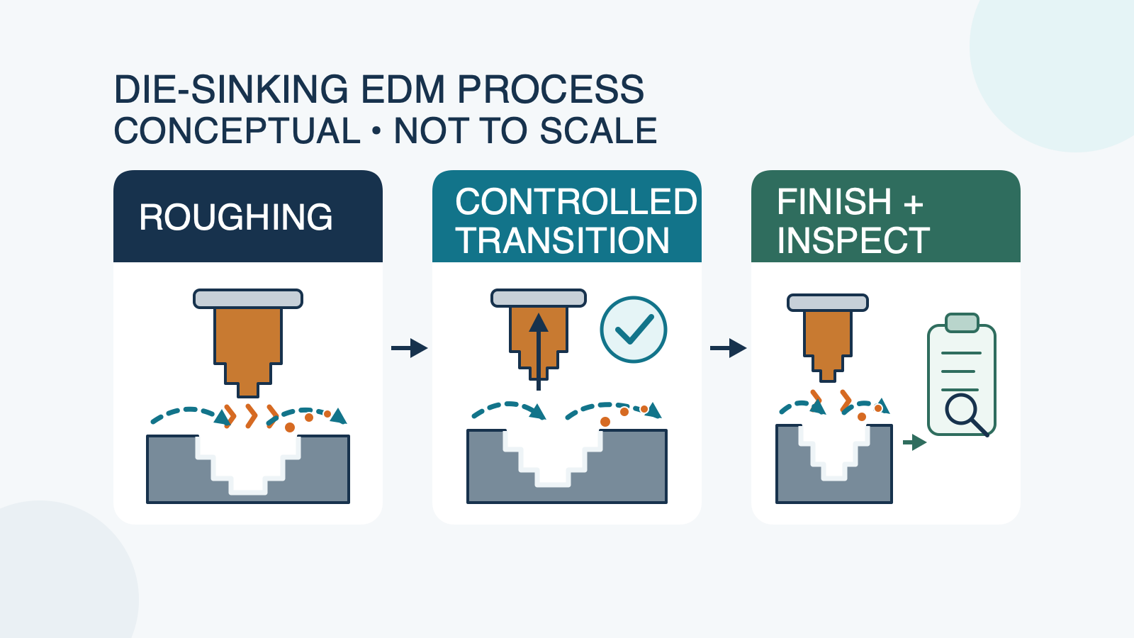
A reliable route is to separate material removal from final surface generation. Use the machine maker's condition tables as the starting point; exact condition codes, current, pulse, voltage, polarity, servo and motion settings are generator- and job-specific.
| Stage | Primary Objective | Controls to Record | Release Check |
|---|---|---|---|
| Roughing | Remove material while leaving the planned allowance for later stages | Electrode identity, polarity, technology condition, depth, flushing path, jump or orbit where supported, and observed stability | Stock allowance, cavity condition, electrode wear and absence of uncontrolled arcing or local damage |
| Semi-finishing | Reduce roughing texture and geometry error before the final burn | Remaining allowance, electrode condition or replacement, compensation, debris removal and the next lower-energy condition | Uniform intermediate surface and sufficient allowance for the finishing stage |
| Finishing | Generate the required final texture while maintaining size and form | Verified finishing condition, finishing electrode, compensation, stable gap, fluid condition, thermal state and full cavity coverage | Roughness, dimensions, corners, taper/form and any specified surface-integrity result |
| Qualification | Prove that the complete process is repeatable before production release | Representative material and geometry, complete parameter revision, electrode history, cycle observations and measurement plan | Documented acceptance against the drawing and process plan |
Do not reduce one setting blindly until the process becomes slow or unstable. Surface quality is produced by the complete discharge condition and gap environment. If the cavity has deep ribs, large engaged area or poor debris escape, it may require a different electrode plan, motion strategy or flushing arrangement rather than only a lower-energy condition.
Select and Prepare the Electrode for the Whole Process
Neither copper nor graphite is universally the best finishing electrode. The result depends on the electrode grade and structure, workpiece material, generator, polarity, current density, cavity geometry, engaged area, flushing and the required balance between speed, wear, detail and finish.
- Record the exact electrode: material and grade, electrode number, roughing or finishing purpose, dimensions, undersize, orientation and holder.
- Inspect before use: check the working faces, edges, ribs, vents, holder interface, runout or alignment, contamination and damage.
- Plan for wear: verify compensation and inspect the actual wear pattern instead of assuming that one nominal offset or one electrode will suit every stage.
- Use separate electrodes where the job requires them: a dedicated finishing electrode can avoid carrying roughing wear and damage into the final surface, but it adds manufacturing, setup and changeover work that must be planned.
- Keep the electrode process consistent: preparation marks, burrs, chips, coatings or contamination can appear as local finish variation.
Automatic wear calculation or compensation should be mentioned only when it is confirmed for the exact controller and configured option. Otherwise, measure and document the electrode and cavity at the stages required by the process plan.
Stabilise the Dielectric, Flushing and Spark Gap
The dielectric insulates the gap before breakdown, cools the process and carries debris away. A finishing condition cannot remain stable if contamination or trapped debris causes repeated abnormal discharges. Use only the dielectric specified or approved for the machine, and follow the machine and fluid suppliers' limits for level, filtration, service condition and temperature.
- check fluid level, circulation, filter condition, visible contamination, leakage and machine indications before diagnosing the electrical settings;
- direct flushing or suction so that debris leaves the active gap instead of collecting in a blind area;
- avoid excessive or uneven flow that disturbs the gap, moves a delicate electrode or creates an inconsistent debris path;
- use jump, orbit or related motion only where the exact machine and controller support it, and qualify the motion with the electrode and cavity geometry;
- do not add powders, surfactants or other chemicals unless the machine and dielectric suppliers have approved the material, concentration, filtration, compatibility and safety procedure.
Gap control is a system response, not a single voltage rule. The generator waveform, ignition behaviour, servo response, electrode area, debris and flushing interact. Persistent arcing, pitting or local overheating should be investigated as a process-stability problem rather than hidden by one arbitrary setting change.
Control Setup and Thermal Variation
Precision finishing can be affected by changes in the machine, workpiece, electrode, dielectric and measurement environment. Follow the selected machine's installation and operating manual, allow the system to stabilise for the required job, and avoid large or rapid environmental changes, direct heating or cooling airflow and uncontrolled measurement conditions.
Before the finishing stages, verify:
- clean and stable locating faces, clamping and workpiece electrical connection;
- the correct datum, depth reference, coordinate revision, compensation and electrode orientation;
- holder and electrode alignment, condition and clearance throughout the planned motion;
- a thermally stable machine, workpiece, electrode and dielectric appropriate to the drawing tolerance and process duration;
- that inspection is performed under the agreed conditions rather than immediately comparing unlike thermal states.
Do not present a universal room or fluid temperature as an EDM rule. The required stability depends on the machine specification, materials, part size, tolerance, cycle duration and measurement plan.
Measure Sinker EDM Surface Finish Correctly
Report Ra and Rz as separate parameters; do not convert one to the other with a fixed factor. For profile surface texture, the current ISO framework includes ISO 21920-2:2021 for terms, definitions and parameters and ISO 21920-3:2021 for specification operators. If the drawing or customer agreement cites another standard or version, follow that documented requirement rather than silently changing it.
A useful inspection record identifies:
- the reported parameter and units;
- standard and version used for acceptance;
- instrument and probe or method;
- filter, cutoff or nesting-index settings required by the applicable method;
- evaluation length, measurement direction and surface locations;
- number of readings and the rule used to accept the result.
Measure enough representative locations to detect directional or local variation. A reading from an accessible flat area may not represent a deep rib, corner or debris-trapping region. When surface integrity is specified, use the agreed metallographic or other inspection method in addition to the texture measurement.
Sinker EDM Finish Troubleshooting Guide
The checks below are diagnostic starting points, not proof of a single root cause. Preserve the last accepted setup, change one controlled variable at a time and repeat the same measurement method.
| Observed Result | Check First | How to Verify |
|---|---|---|
| The whole cavity is rougher than the accepted baseline | Program/condition revision, completion of every finishing stage, electrode identity and wear, dielectric/filter condition and measurement method | Repeat a representative test with the last accepted documented condition and the same instrument setup |
| Local pits, burn marks or arcing | Debris trapping, blocked or uneven flushing, electrode damage, unstable gap, workpiece/electrode contact and inappropriate condition for the engaged area | Inspect the affected geometry and electrode, restore the approved fluid/debris path and perform a controlled trial before returning to the part |
| Bands, patches or finish that changes with depth | Stage transition, electrode wear pattern, cavity venting, fluid access, jump/orbit support and depth-dependent debris removal | Map measurement locations and compare them with geometry, depth and electrode condition |
| Finish is acceptable but size, taper or form drifts | Datum and clamping, electrode undersize/wear, compensation, alignment, thermal state and measurement conditions | Inspect dimensions and form separately from roughness using the agreed datum and stabilised measurement condition |
| Finishing is unusually slow or unstable | Whether the selected condition matches the generator/material/area, debris removal, filter and fluid condition, electrode condition and gap motion | Compare cycle observations, interruptions and surface results with a documented representative feature |
| Ra passes but a critical surface still fails | Rz/other specified parameters, recast-layer or microcrack requirement, dimensions, coating or downstream process, and inspection coverage | Apply the drawing's full dimensional, texture and surface-integrity acceptance plan |
If the problem involves the generator cabinet, axis feedback, safety circuit, fire-protection system, machine geometry or an unresolved alarm, stop and use authorised service support. Do not bypass interlocks or instruct an operator to repair high-energy electrical equipment.
Choose the Machine and Prepare a Useful RFQ
HarsMarg lists die-sinking EDM machines in both ZNC die-sinking EDM and CNC die-sinking EDM categories. Surface-finish suitability cannot be selected from tank size or generator current alone. The controller, axis and motion requirements, electrode/workpiece envelope, load, cavity geometry, process stages, inspection plan and required options all need to be reviewed for the actual application.
For a technical quotation or process discussion, send:
- a drawing or 3D model showing cavity size, depth, projected area, ribs, corners, tolerances and required finish zones;
- workpiece material, grade, hardness/condition, overall dimensions and weight;
- required Ra, Rz and the measurement standard/method, plus any surface-integrity limit;
- electrode material/grade, number of electrodes, dimensions, undersize and holder information if already defined;
- current process, machine/controller, dielectric, roughing/finishing sequence and the observed defect or bottleneck;
- production volume, required inspection records, automation or unattended-operation needs;
- destination country, available power supply and applicable plant or safety requirements.
If an exact finish capability is required in the purchase specification, request a documented trial on representative material and geometry with agreed electrode, condition sequence and measurement method. A competitor's best-case sample or an uncited catalogue number is not a substitute for a HarsMarg model-specific acceptance test.
Frequently Asked Questions
Does reducing current always improve sinker EDM surface finish?
No. Finishing generally uses lower discharge energy than roughing, but the stable result depends on the complete generator condition, electrode/workpiece pair, engaged area, servo response, fluid and debris environment. An arbitrary reduction can make the process unstable or unnecessarily slow. Start with the exact machine's technology table and qualify the full sequence.
Is copper or graphite better for fine sinker EDM finishing?
Neither is universally better. Electrode grade, structure, machinability, detail, wear behaviour, workpiece material, polarity, generator and cavity geometry all matter. Compare the complete process and required result rather than selecting by material name alone.
Does a low Ra value mean there is no recast layer or microcracking?
No. Ra describes one aspect of surface topography. Recast-layer thickness, microcracking and other surface-integrity features require their own drawing limits and inspection method when they are functionally important.
How many roughing and finishing stages are required?
There is no universal number. It depends on starting allowance, cavity size and depth, engaged area, electrode plan, generator, material, target texture, dimensional tolerance and surface-integrity requirement. Use the model-specific technology guidance and confirm the sequence with a representative trial.
Can powders or additives be used to improve the finish?
Only when the exact machine and dielectric suppliers approve the material, concentration, circulation, filtration, compatibility, fire/safety controls and disposal method. A proprietary OEM process or published experiment is not a generic recipe for another machine.
What should be inspected after a sinker EDM finishing trial?
Inspect the specified texture parameters at agreed locations, cavity dimensions and form, corners and radii, taper where relevant, electrode wear and any required recast-layer or microcrack criteria. Record the complete process revision and measurement method so the accepted result can be reproduced.
Request a Sinker EDM Process Review
Send your drawing, material, cavity geometry, tolerance, required surface texture and integrity criteria, electrode plan, production volume, destination and power supply. HarsMarg can review the relevant machine family and identify which capability and sample-test conditions must be confirmed in the technical quotation. Submit your sinker EDM application for review.
Table of Contents
- Surface Finish and Surface Integrity Are Not the Same
- Define the Acceptance Method Before Changing Settings
- Use a Controlled Roughing-to-Finishing Sequence
- Select and Prepare the Electrode for the Whole Process
- Stabilise the Dielectric, Flushing and Spark Gap
- Control Setup and Thermal Variation
- Measure Sinker EDM Surface Finish Correctly
- Sinker EDM Finish Troubleshooting Guide
- Choose the Machine and Prepare a Useful RFQ
-
Frequently Asked Questions
- Does reducing current always improve sinker EDM surface finish?
- Is copper or graphite better for fine sinker EDM finishing?
- Does a low Ra value mean there is no recast layer or microcracking?
- How many roughing and finishing stages are required?
- Can powders or additives be used to improve the finish?
- What should be inspected after a sinker EDM finishing trial?
- Request a Sinker EDM Process Review