EN
EN



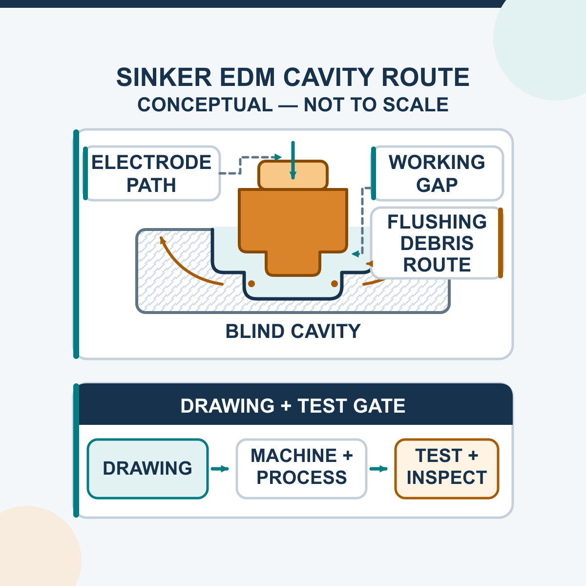
The main advantage of sinker EDM is its ability to produce blind cavities and complex formed features in electrically conductive materials without a conventional cutting edge pressing against the workpiece. It is often a strong candidate for molds, dies, hardened tooling and details that are difficult to reach or control by milling. Its actual accuracy, surface finish, cycle time and cost still depend on the machine, electrode, workpiece, cavity, spark gap, dielectric system and qualified process.
Sinker EDM is therefore best evaluated as an application-specific process, not as a universal replacement for milling or Wire EDM. A useful selection review starts with the drawing, material, cavity geometry, electrode plan, production volume and acceptance method. It does not start with an unconditional tolerance or surface-finish number.
How Sinker EDM Produces a Cavity
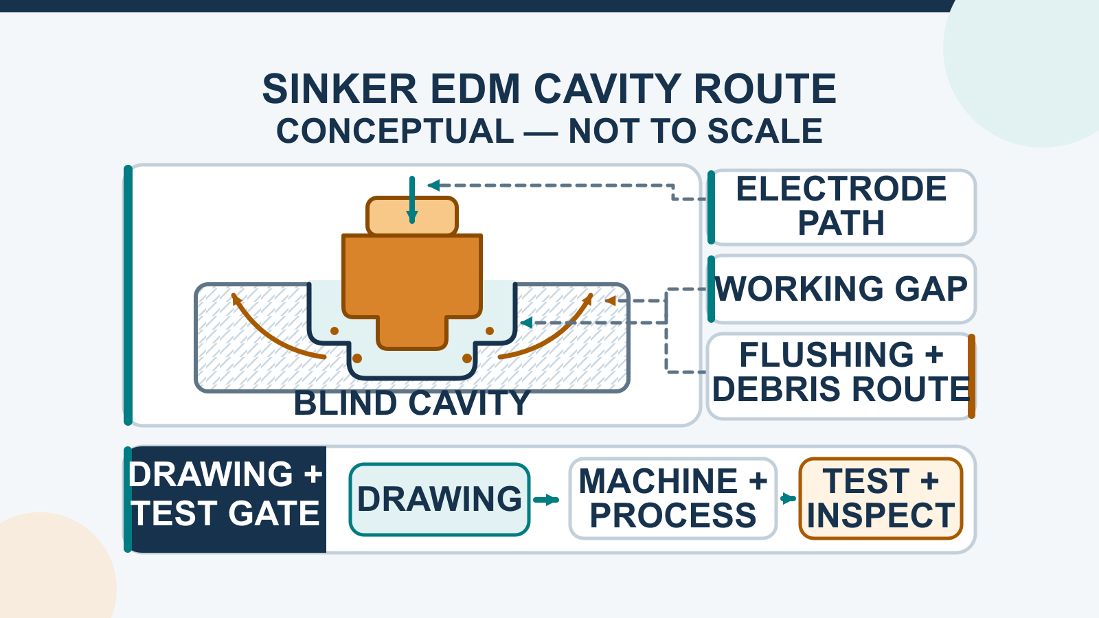
A die-sinking or ram EDM machine creates controlled pulsed electrical discharges across a small gap between a shaped electrode and the workpiece. The active area is surrounded by dielectric fluid. Each discharge removes a small amount of material, and the servo system maintains a usable gap as the electrode advances.
The workpiece generally must be electrically conductive. Mechanical hardness is less restrictive than it is for a chip-forming cutting tool, but removal rate is not independent of the material: melting behaviour, electrical and thermal properties, electrode/workpiece pairing, discharge conditions, engaged area and debris removal all matter.
The cavity follows the designed electrode form, but it is not a perfect one-to-one copy. The electrode is normally designed with a deliberate undersize or offset for the discharge gap. Its material, surface, corner radii, wear, alignment, compensation and any supported orbital motion affect the final size and form.
The Practical Advantages of Sinker EDM
Each advantage below has a process boundary. The final column identifies what should be confirmed before the benefit becomes a purchasing or production claim.
| Potential Advantage | Where It Helps | What Must Be Confirmed |
|---|---|---|
| Blind and formed cavities | Mold cavities, die details, recesses, ribs and other features that do not pass through the workpiece | Electrode access, cavity depth and area, debris path, smallest radii and electrode-manufacturing feasibility |
| Hardened conductive materials | Parts where cutting-edge wear, tool pressure or machining after heat treatment makes conventional cutting difficult | Exact material/grade and condition, electrode pair, qualified technology condition, expected speed and surface-integrity requirement |
| No conventional cutting force at the discharge interface | Features where cutter pressure or chatter would be undesirable | Workholding, support, part stress history, thermal stability and representative-part validation |
| Controlled roughing and finishing stages | Jobs requiring a planned balance of removal rate, geometry and final texture | Generator/process table, stock allowance, electrode sequence, wear compensation, measurement method and any later polishing |
| Repeatable cavity production | Repeat work where datums, electrodes and process records can be controlled | Machine configuration, electrode consistency, setup method, gap stability, thermal control, inspection and documented change control |
| Automation potential | Long cycles or repeated work where supported electrode/workpiece handling and monitoring can improve utilisation | Exact CNC, changer, monitoring, fire-protection, recovery and safety configuration; no unattended claim should be assumed from the process name |
When Is Sinker EDM a Strong Fit?
The drawing and process route should decide the technology. The comparison below is a screening guide, not a substitute for application review.
| Usually a Strong Sinker-EDM Candidate | Consider Another or Hybrid Process | Selection Question |
|---|---|---|
| Blind cavity or shaped recess in a conductive workpiece | Simple open geometry that a standard milling tool can reach efficiently | Does the cavity justify a dedicated form electrode and EDM cycle? |
| Deep/narrow or detailed feature with a feasible electrode and debris path | Geometry with no practical electrode access, flushing/debris route or stable gap | Can the electrode, holder and fluid path reach and clear the full feature? |
| Hardened conductive material that is difficult to cut mechanically | Non-conductive material without a specifically validated assisted process | Is the exact material electrically machinable under the proposed process? |
| Repeated cavity work where electrode/setup cost can be planned | One-off work where electrode manufacture and qualification exceed the benefit | What is the complete cost per accepted part, including electrodes and inspection? |
| Feature requiring a formed blind cavity | Through-cut profile better suited to Wire EDM | Is the required geometry blind/formed or a through profile? |
| Surface-integrity limits that can be qualified and inspected | Application that rejects the resulting thermal layer and does not allow an approved finishing/removal step | What recast, crack, residual-stress or downstream-process requirement applies? |
Accuracy and Surface Finish Are Qualified Outcomes
Sinker EDM can support precise cavity work, but no single tolerance applies to every machine and job. The result depends on machine positioning and thermal behaviour, the manufactured electrode, undersize, electrode wear, spark gap, cavity depth and area, roughing/finishing allowance, datum strategy and inspection.
Surface texture must also be defined rather than described only as “smooth” or “mirror.” Record the required parameter, such as Ra or Rz, its units, the standard and version, measurement direction, locations, instrument settings and acceptance rule. Do not convert Ra and Rz with a fixed factor.
A smoother measured texture does not prove that the part has no recast layer, heat-affected material or microcracking. Those are surface-integrity questions and require their own limits and inspection when they affect fatigue, sealing, coating, corrosion, medical use or another critical function. See the separate sinker EDM surface-finish process guide for a controlled roughing-to-finishing and measurement workflow.
Electrode Design Determines More Than the Nominal Shape
The electrode is a manufactured process tool. Its material and grade, particle structure where graphite is used, strength, machinability, thermal behaviour and wear resistance affect detail, speed, finish and total job cost. Copper and graphite each have useful applications; neither is universally best.
A production electrode plan should define:
- electrode material and exact grade, manufacturing method and inspection record;
- nominal form, minimum ribs/radii, surface condition and features used for debris removal;
- qualified undersize/offset, polarity and compensation strategy;
- roughing, semi-finishing and finishing roles, including whether separate electrodes are required;
- holder, datum, alignment, orientation and exchange procedure;
- corner, end and side wear checks and the replacement/requalification rule.
The smallest practical internal radius is therefore not zero. It is governed by electrode manufacture and radius, spark gap, wear, depth, compensation and process stability. If the drawing has a critical internal corner, put the radius and inspection rule on the drawing and include it in the sample trial.
Deep Cavities Need a Gap and Debris-Removal Plan
The dielectric insulates the gap before breakdown, cools the active region and carries removed particles away. A process that works on an open shallow cavity may not remain stable in a deep rib or large blind area. Trapped debris can contribute to abnormal discharges, local pitting, slower machining, additional wear and non-uniform surfaces.
Before accepting a deep or narrow cavity, review:
- the full electrode and holder access throughout the planned depth;
- approved dielectric, fluid level, filtration, circulation and service condition;
- where debris enters, moves and leaves the active gap;
- flushing, suction, jump or orbit only where the selected machine and controller support it;
- whether flow or motion could disturb a delicate electrode or create uneven conditions;
- how wear, taper, depth and surface will be measured in the least accessible area.
Do not transfer a fluid type, pressure, conductivity, temperature, jump amount, orbit value or electrical setting from another machine. Use the supplied manual and technology table for the exact configuration, then qualify the complete process on representative geometry.
No Conventional Cutting Force Does Not Mean “Stress-Free”
Because the electrode and workpiece do not make conventional cutting contact, sinker EDM avoids the cutter pressure and chip-forming chatter associated with milling. That can be valuable for delicate features and hardened materials. It does not eliminate the need for secure workholding, correct support, stable datums or thermal control.
EDM is a thermal process. Material melts or vaporises locally, most debris is removed by the dielectric, and some material may resolidify at the surface as a recast or white layer. Heat-affected material, residual stress or microcracking may also matter for the application. Roughing and finishing conditions can change these outcomes, but “no metallurgical change” and “stress-free” are not valid general descriptions.
Evaluate Production Efficiency by Accepted Part, Not Burn Time Alone
Sinker EDM can reduce handling or manual finishing in a qualified process, but it is not automatically the fastest or least expensive method. Conventional milling is often faster for simple accessible geometry. EDM adds electrode design and manufacture, setup, dielectric and filtration, burn time, electrode wear, inspection and possible polishing or recast-layer removal.
The economic comparison should include the complete route: electrode count and fabrication time, fixture and setup, machine cycle, operator attendance, consumables, inspection, rejected parts, secondary finishing and the number of accepted parts. Repeat cavities may justify a more developed electrode and automation strategy; a one-off cavity may not.
HarsMarg groups its current machines under the die-sinking EDM range, with separate ZNC die-sinking EDM and CNC die-sinking EDM categories. Selection should be based on verified control architecture, axis travel, tank/workpiece envelope, load, generator, electrode requirements, motion and options for the actual drawing. A CNC label alone does not prove automatic electrode changing, unattended operation or a particular accuracy/finish.
Qualify the Process on a Representative Sample
When tolerance, finish, surface integrity, cycle time or electrode wear is important, use a documented sample test rather than a generic catalogue claim. The sample should represent the actual material and the features most likely to control the result.
- Freeze the requirement: material/condition, geometry, tolerances, texture, surface-integrity limits, production volume and inspection method.
- Define the electrode: material/grade, geometry, undersize, holder, datum, number and roughing/finishing role.
- Use the exact proposed configuration: machine, generator, controller, dielectric system, supported gap/debris strategy and approved process table.
- Record the complete run: process revision, stages, stability observations, cycle time, electrode identity/wear and any interruption or corrective action.
- Inspect against the drawing: dimensions, form, depth, taper, radii and texture, plus surface integrity where specified.
- Release only the proven scope: state the material, geometry, conditions and measurement boundary instead of converting one test into a universal machine claim.
What to Send for Machine Selection or an RFQ
A useful technical review needs more than the overall part size. Send:
- a 2D drawing and, where available, a 3D model with datums and revision;
- workpiece material, grade, heat-treatment/hardness condition, dimensions and weight;
- cavity opening, depth, projected or engaged area, ribs, vents, corners and required internal radii;
- dimensional/form tolerances and the areas to which they apply;
- required Ra, Rz or other texture parameter, units, standard/version and measurement method;
- any recast-layer, microcrack, residual-stress, polishing, coating or other surface-integrity requirement;
- existing electrode concept or required help with material, grade, undersize, number and holder;
- annual or batch quantity, target cycle, inspection record and automation needs;
- destination country, available power supply and applicable plant/safety requirements.
For a model review, sample-test plan or technical quotation, contact HarsMarg with the drawing and material information. Any acceptance figure should be written against the confirmed model, configuration, sample and inspection method.
Frequently Asked Questions
What is the biggest advantage of sinker EDM?
Its defining advantage is the ability to use a shaped electrode to create a blind or formed cavity in an electrically conductive workpiece without conventional cutting contact. This is especially useful when the material is hardened or the feature is difficult to reach with a cutter. The result still depends on the electrode, gap, debris control and qualified process.
How is sinker EDM different from Wire EDM?
Sinker EDM uses a shaped electrode to form a cavity or recess. Wire EDM uses a moving wire electrode to cut a profile, normally through the workpiece. A blind mold cavity usually points toward sinker EDM; a through-cut contour may point toward Wire EDM. The drawing and access path decide the process.
Can sinker EDM machine any material?
The workpiece generally must be electrically conductive. Even among conductive materials, removal rate, electrode wear, finish and surface integrity vary with the grade and condition. Confirm the actual material and process rather than relying only on the word “metal.”
Is sinker EDM accuracy independent of material hardness?
No. Mechanical hardness is less restrictive because there is no conventional cutting edge, but material electrical/thermal behaviour, electrode pairing, discharge conditions, geometry, gap stability, wear and inspection still affect the result. Accuracy must be qualified for the actual job.
Does no cutting contact mean the part is stress-free?
No. Sinker EDM avoids conventional cutter pressure and chatter, but it is a thermal process. Recast/white layer, heat-affected material, residual stress or microcracking may matter, and the part still needs suitable support and clamping.
Can every sinker EDM produce a mirror finish or the same tight tolerance?
No. Fine finish and tight cavity results depend on the machine and generator, electrode material/grade and surface, undersize, workpiece, cavity size/depth, fluid/debris control, process stages, thermal conditions and measurement method. Ask for a representative documented trial when the requirement is important.
Is copper or graphite always the better electrode?
Neither is universally better. Compare the exact material and grade against the workpiece, detail, surface target, generator, polarity, wear, electrode-manufacturing route and total accepted-part cost.
Table of Contents
- How Sinker EDM Produces a Cavity
- The Practical Advantages of Sinker EDM
- When Is Sinker EDM a Strong Fit?
- Accuracy and Surface Finish Are Qualified Outcomes
- Electrode Design Determines More Than the Nominal Shape
- Deep Cavities Need a Gap and Debris-Removal Plan
- No Conventional Cutting Force Does Not Mean “Stress-Free”
- Evaluate Production Efficiency by Accepted Part, Not Burn Time Alone
- Qualify the Process on a Representative Sample
- What to Send for Machine Selection or an RFQ
-
Frequently Asked Questions
- What is the biggest advantage of sinker EDM?
- How is sinker EDM different from Wire EDM?
- Can sinker EDM machine any material?
- Is sinker EDM accuracy independent of material hardness?
- Does no cutting contact mean the part is stress-free?
- Can every sinker EDM produce a mirror finish or the same tight tolerance?
- Is copper or graphite always the better electrode?