EN
EN



Planning an Accurate Complex Contour
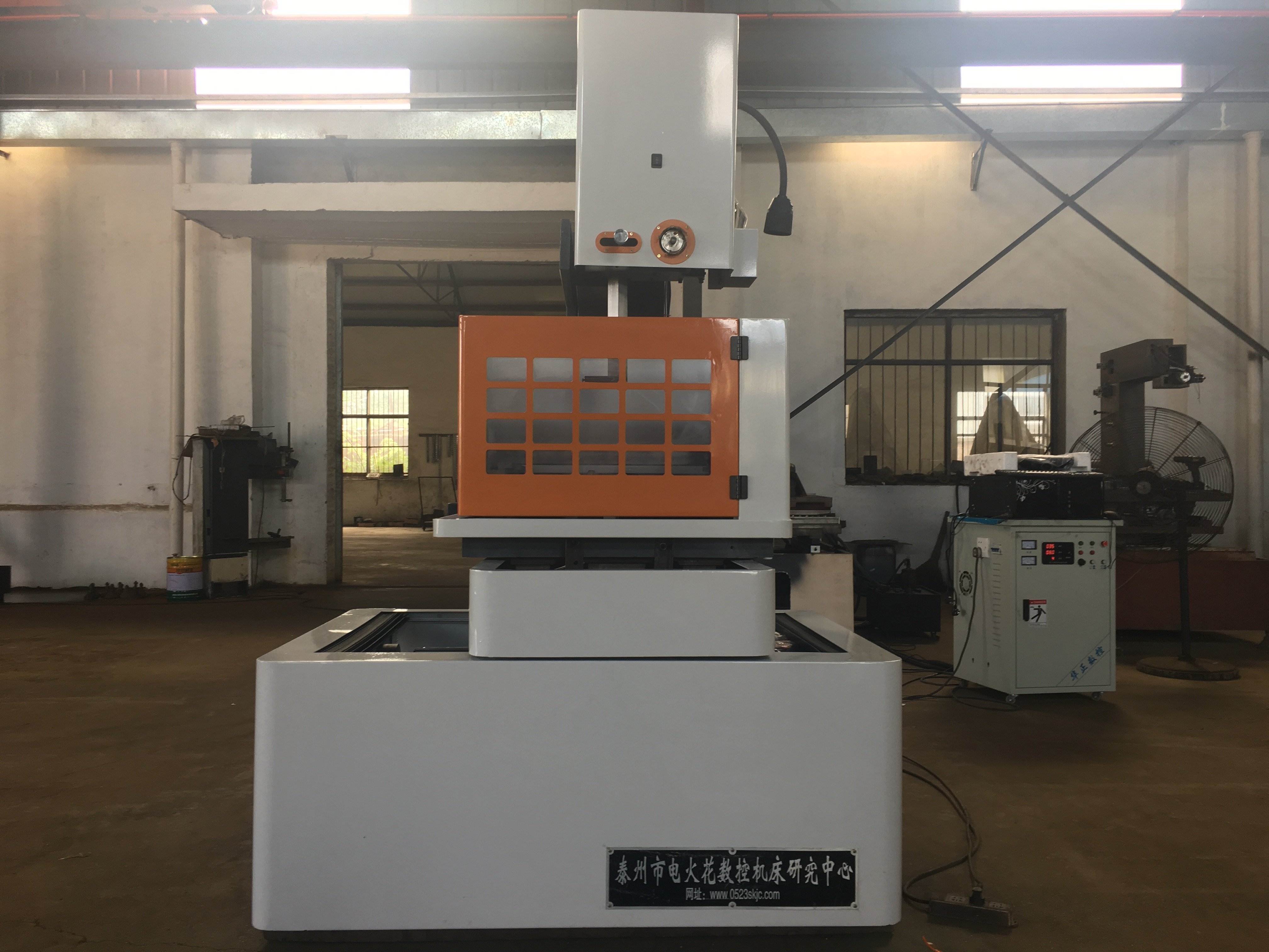
Wire EDM equipment can be considered for complex profiles in suitable conductive workpieces. The wire electrode follows a programmed path while controlled electrical discharges remove material. An accurate result requires a feasible cutting route, suitable machine configuration and inspection against the drawing; the shape or axis count alone does not establish a finished-part tolerance.
Start by specifying the material grade, thickness, required contours, dimensions and surface requirements. Include corner radii, narrow slots and the top and bottom profiles where relevant. Review how the wire enters the cut, how the part is held and what happens when a section separates. Non-contact cutting is not proof that every geometry is accessible or free from dimensional variation.
Core Components of Wire EDM Systems
Wire Specification and Cutting Path
Confirm the wire-motion system, approved wire material and diameter for the proposed machine. Review the wire entry path and any required starting hole for an internal profile. A reciprocating-wire arrangement should not be described as a single-direction fresh-wire system, and automatic threading should not be assumed from CNC control alone.
Choose the wire within the machine's permitted specification and evaluate it on the required material, thickness and contour. Wire composition, a coating or a tension setting does not by itself establish the achievable dimensions or surface finish. Keep the selected wire and cutting conditions with the representative part's inspection record.
Working Fluid and Flushing
Confirm the specified working fluid, filtration and maintenance requirements for the actual equipment. Review access for flushing around the contour and fixture. Do not transfer a deionized-water specification or an oil-based system's requirements to every wire EDM design.
If flow, pressure, temperature or fluid-condition control is offered, identify what is measured and adjusted. Follow the machine instructions for maintaining suitable conditions. These functions can support the proposed process within their scope, but do not guarantee the contour's accuracy or uninterrupted cutting.
Precision Control and Motion Systems
Program Datum and Positioning
Prepare the CNC path from the required geometry and verify the datum, fixture and machine settings. Confirm how the program accounts for wire size and the proposed discharge-gap allowance. Keep command resolution, positioning accuracy, repeatability and cut-part dimensions separate; a positioning specification does not establish that every cut feature meets the drawing.
Where adaptive discharge or process control is supplied, confirm its inputs, permitted adjustments and operating limits. Selecting or adjusting machining conditions is not the same as automatically identifying every material or measuring the finished contour. Inspect the part using the agreed dimensional and surface criteria.
Axis Configuration and Taper
For angular cuts, identify the actual controlled axes, guide arrangement and taper limits at the required workpiece height. If upper and lower contours differ, review both profiles and the proposed motion together. An axis count is not a description of which motions can operate simultaneously or which complex shapes can be completed.
Check travel, fixture clearance, wire access and workpiece support throughout the route. Where temperature control or compensation is available, confirm its scope and required environmental conditions. Evaluate the completed contour rather than treating rigidity or compensation as a guarantee of constant accuracy over a long run.
Surface Quality and Accuracy Verification
Cutting Passes and Part Acceptance
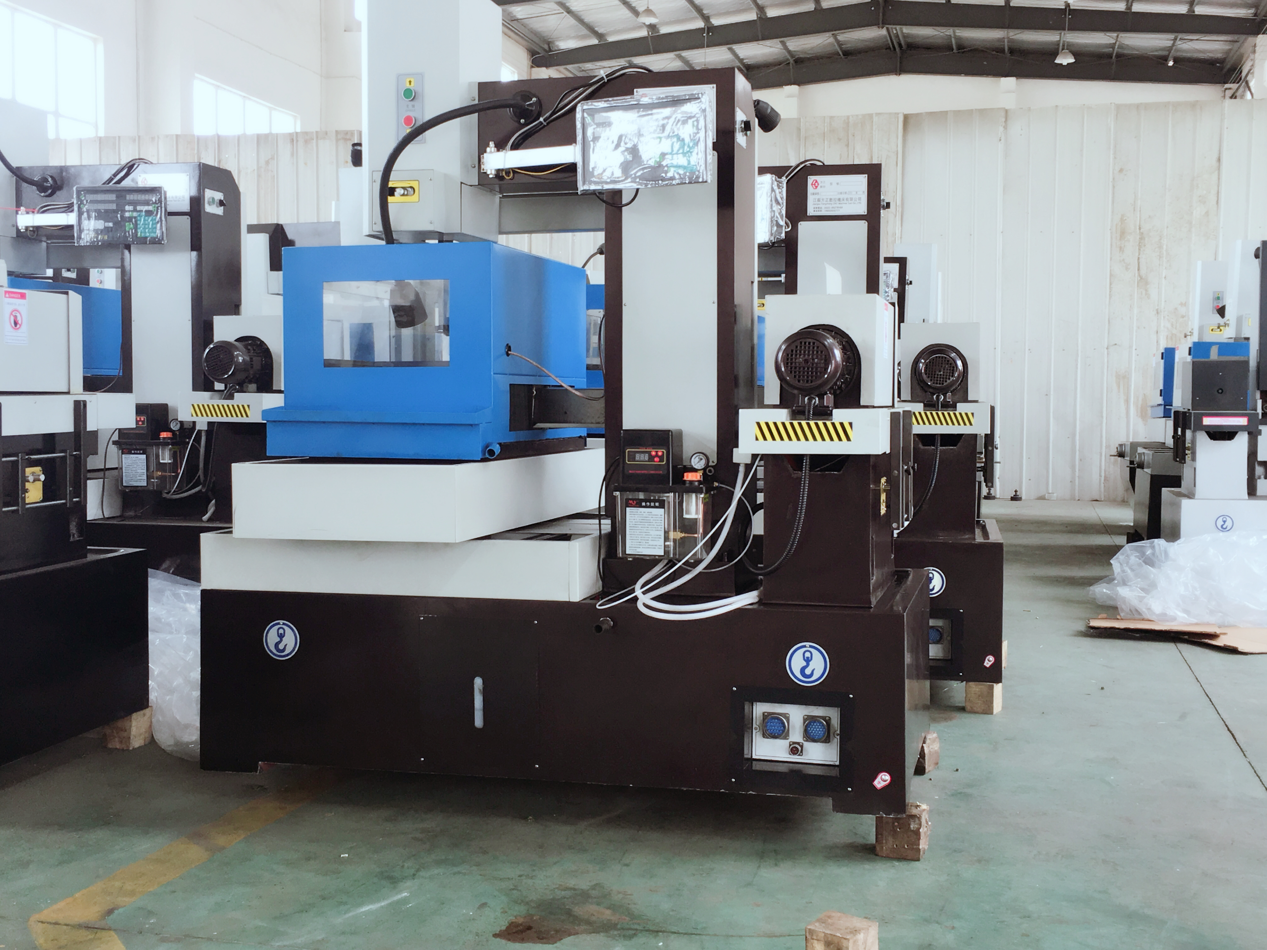
Choose cutting passes and discharge settings within the machine's supported process for the job. Dimensional tolerance, roughness and surface integrity are separate acceptance requirements. A smooth-looking cut or a roughness value alone does not confirm the accuracy or suitability of the part.
Compare any proposed speed or finish improvement under stated conditions: material, thickness, wire, contour, cutting passes, settings and measurement method. Include required finishing in the route. The suitable balance depends on the drawing and acceptance criteria, not a universal best surface finish or cutting rate.
Threading and Recovery Conditions
If automatic threading or rethreading is proposed, confirm the supported starting-hole, wire-path and workpiece conditions. Plan how interruptions and separated cores will be handled under the equipment instructions. A demonstrated threading cycle is not evidence that every complex profile can run without operator intervention.
Follow the approved recovery procedure after a wire break or other interruption. Check the restart area and completed part before acceptance. Monitoring and parameter control do not eliminate the possibility of faults or replace inspection of the cut dimensions and surface.
Frequently Asked Questions
What is the maximum cutting accuracy achievable with wire EDM equipment?
There is no single cutting-accuracy value applicable to every machine and part. Positioning accuracy describes machine motion; finished-part accuracy must be checked on the cut geometry, and roughness is a separate surface measure. Provide the required tolerance, material, thickness and contour, then confirm the proposed configuration, process and inspection method. Maintenance and environmental conditions remain relevant.
How does wire EDM equipment handle different material types?
Electrical conductivity is an initial screening condition, not a guarantee that every material can be cut with the same result. Confirm the material grade, heat-treatment state, thickness and required geometry. Use suitable wire, fluid and cutting conditions for the actual machine; cutting time, finish and dimensional results depend on the job and should be evaluated separately.
What maintenance requirements are necessary for wire EDM equipment?
Follow the machine's maintenance instructions for wire-handling parts, working fluid, filtration, guides and motion-system checks. Use qualified service for any required calibration or adjustment. If condition monitoring is available, confirm its signals and response; a reminder or monitoring display is not proof of predictive maintenance or protection against every unexpected stop.