EN
EN



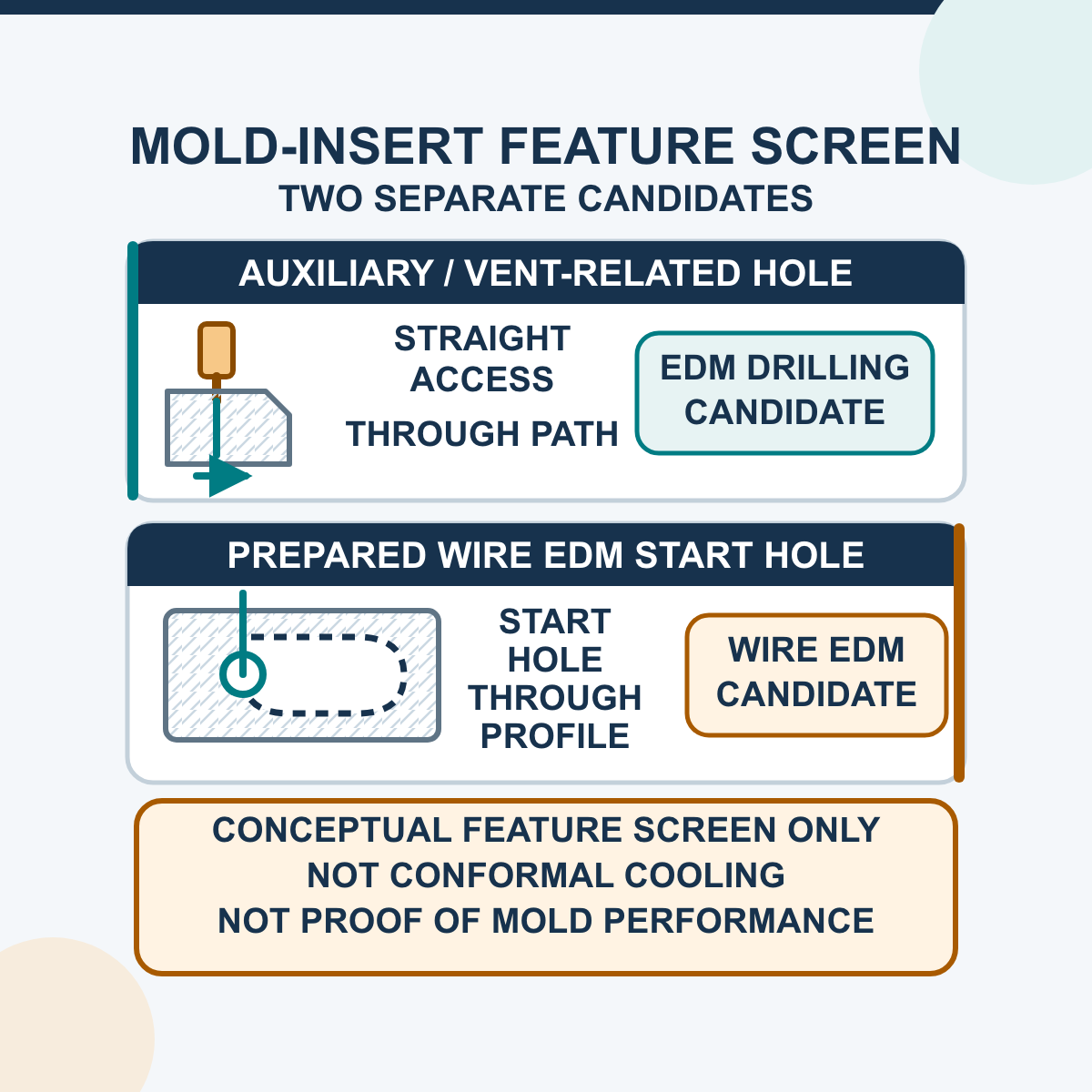
Small-hole EDM can support mold and die production when a released drawing requires a small or deep feature in sufficiently conductive material and the feature is difficult to produce with a conventional cutting tool. Typical candidates include a through start hole for a later Wire EDM cut and some straight auxiliary holes in a mold insert. The benefit is conditional: the process does not automatically create a conformal cooling circuit, correct a venting problem, shorten a molding cycle or extend mold life.
A useful process decision begins with the finished feature—not the electrode catalogue. Define what the hole must do, where it enters and exits, what it may intersect, which datums control it, and how it will be measured. Then select the electrode, guide, fixture, flushing approach, machine configuration and inspection plan around that requirement.
Identify the Feature Before Choosing the Process
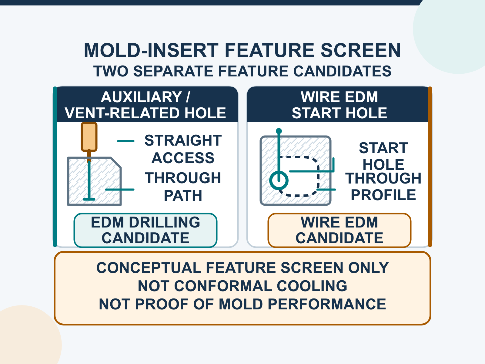
“A small hole in a mold” can describe very different tasks. The feature's function changes the machining and acceptance questions.
| Feature family | Why EDM drilling may be evaluated | Conditions to define | Do not assume |
|---|---|---|---|
| Wire EDM start hole | Provides a through path for threading the wire before the programmed profile is cut. | Start location, thickness, entry/exit access, wire-threading clearance, relation to the final contour and disposable slug condition. | That a nominal electrode automatically gives the required clearance or that every internal profile has safe exit access. |
| Small straight through hole | May be useful in hardened or difficult-to-cut conductive inserts when geometry and access suit the process. | Finished diameter definition, depth, entry surface, exit condition, position, axis direction, form and surface-integrity limit. | Perfect straightness, identical entrance and exit, no thermal effect or a burr-free edge without inspection. |
| Cooling- or flow-related auxiliary hole | A straight drilled segment or intersection may be one part of a released circuit where the material and access are suitable. | Circuit drawing, intersections, plugs/seals, wall thickness, cleaning access, leakage/flow test and protected surfaces. | That drilling alone creates a curved conformal channel or guarantees a molding-cycle improvement. |
| Vent- or gas-relief-related hole | May be considered when the mold designer specifies a drilled conductive path and an outlet. | Vent function, outlet, flash/sealing constraints, blockage risk, service access and functional molding validation. | That adding a hole eliminates burns, short shots or trapped gas regardless of the mold and process. |
| Repeated coordinate pattern | Programmed positioning may help when many locations share a controlled datum scheme. | Coordinate list, datum transfer, fixture repeatability, setup verification, sample size and position inspection. | That CNC positioning proves finished-hole size, form or functional performance. |
Screen Material, Geometry and Access
Before selecting an EDM drilling workflow, record the actual mold material and feature geometry. Electrical conductivity is required, but conductivity alone does not establish a stable or acceptable result.
- Material: state the grade, heat-treatment/condition, coating or surface layer, and whether the workpiece has been finish-machined.
- Geometry: define finished diameter, total depth, through/blind/intersecting condition, entry angle and any protected wall or cavity beyond breakthrough.
- Access: confirm that the electrode, guide and fluid path can reach the feature without collision and that the fixture supports the required direction.
- Datums: identify which surfaces or features locate the hole and how those datums transfer from design, setup and inspection.
- Function: state whether the hole is for wire threading, flow, venting, access, alignment or another released purpose; each function has a different acceptance plan.
Angled entry, a curved surface, a blind termination, a cavity or a back wall can change flushing, guide support and breakthrough risk. Do not promise these conditions from a generic machine description. Confirm the quoted axes, fixture, guide arrangement and any protection/detection function for the exact configuration.
Treat a Wire EDM Start Hole as Part of the Whole Cut
For an internal profile, the drilled hole is the entry point for the later Wire EDM operation. The hole is useful only if the wire can be threaded through it and the downstream cut can begin without damaging a retained surface. Review the start-hole location with the final contour, cut direction, slug/support plan and workholding—not as an isolated diameter.
The release record should identify:
- the applicable drawing/profile revision and start-hole coordinate;
- workpiece material, condition and thickness at the drilling location;
- required wire-threading clearance and the actual wire/threading method;
- entry and exit access, breakthrough result and any protected surface;
- the relation between the hole and material that the later profile cut will remove.
A start hole may lie inside stock that will later become scrap, so its functional acceptance can differ from a finished flow or vent hole. That distinction belongs on the drawing or process plan.
Separate Hole Making From Mold Performance
An EDM drilling machine produces a hole feature; it does not validate the entire cooling or venting design. A cooling-related feature still requires the mold engineer to verify circuit routing, spacing from functional surfaces, remaining wall strength, intersections, plugs/seals, cleaning access and the agreed leak/flow test. A vent-related feature requires an outlet, flash and sealing review, clogging/maintenance plan and molding trial under the released process.
Do not report reduced cycle time, fewer burn marks, lower scrap, longer mold life or improved part dimensions as a drilling result unless a defined before/after study controls the mold, material, machine settings, process window, sample size and measurement method. These are system outcomes, not automatic consequences of a small hole.
Control Electrode Wear, Flushing and Thermal Effects
EDM avoids a conventional cutting edge, but the electrode is still a consumable. Its outside/inside geometry, material, wear, runout and usable supported length influence the drilled feature. Guide alignment and condition influence the electrode path. The nominal electrode size therefore cannot be copied into the drawing as the finished-hole result.
Working fluid supports discharge-gap recovery, cooling and debris evacuation. As depth increases or the debris path becomes restricted, unstable discharge, side erosion, taper and interruptions may become more difficult to control. Record the actual fluid/filtration condition, flushing arrangement, guide/electrode combination and process-parameter revision used for the accepted sample. If the process uses water on corrosion-susceptible mold steel, include the approved cleaning, drying and rust-prevention method.
EDM is a thermal process. When the feature's function or customer specification makes surface integrity important, define how recast/white layer, heat-affected material or microcracks will be assessed. A visually open hole is not proof that the metallurgical requirement is satisfied.
Choose the D703 or DD703 Workflow From the Job
The current English HarsMarg pages list a φ0.3–φ3.0 mm electrode-diameter range for both models. This is a tooling field—not a guaranteed finished-hole range. Select the machine from the setup and positioning workflow, then validate the feature.
| Selection point | D703 | DD703 |
|---|---|---|
| Control positioning | Non-CNC single-axis machine; the controlled/servo feed axis is Z. Workpiece location and the fixture/setup plan must manage the other positioning needs. | CNC/multi-axis family for programmed coordinate positioning. Confirm the axes, travel, datum method and supplied configuration in the quotation. |
| Workflow fit to evaluate | Simpler setup-managed work or an individually located feature where the operator/fixture controls positioning. | Repeated coordinate patterns or jobs that require programmed movement between locations. |
| Still requires proof | Finished diameter, depth, position, direction, taper/straightness, form, entry/exit condition, surface integrity, repeatability and cycle behaviour all remain application-specific. | |
Compare the current EDM hole drilling machine range. Do not infer rotary axes, automatic tool/guide change, automatic edge finding, back-wall protection, unattended operation or another option unless it appears in the configuration being quoted.
Qualify the Representative Mold Feature
- Freeze the requirement. Record the drawing revision, feature function, datums, finished geometry, sample quantity, measurement method and acceptance rule.
- Select a representative sample. Use the actual material/condition and include the most demanding relevant depth, entry surface, intersection, breakthrough or protected-wall condition.
- Record machine and setup. Identify the model/configuration, fixture, datum transfer, guide, electrode identity and lot, usable length, alignment and runout checks.
- Record process condition. Identify the approved parameter revision, working fluid and condition, filtration, flushing arrangement, electrode rotation/feed observations and any interruption.
- Track consumable behaviour. Record holes per electrode, wear, replacement/dressing and breakthrough behaviour; do not convert one successful hole into a model-wide capability.
- Inspect dimensional and functional outputs. Use equipment suited to the feature and include uncertainty/decision rules when a result is close to a limit.
- Release a bounded process. Keep the accepted material, geometry, electrode/guide, setup, parameter/fluid condition and inspection plan together. Revalidate when a material, depth, entry condition or required result changes materially.
| Acceptance item | Definition needed | Possible evidence |
|---|---|---|
| Size and form | Where diameter applies; roundness/cylindricity; taper or straightness requirement. | Entrance/exit readings plus an agreed internal-section or non-destructive method when depth variation matters. |
| Location and direction | Datums, coordinate/position tolerance and hole-axis orientation. | A controlled dimensional report tied to the drawing revision and setup datums. |
| Entry, exit and breakthrough | Permitted edge condition, exit location and protected back wall/cavity. | Visual/metrology record and a section or other agreed method where hidden damage matters. |
| Surface integrity | Named surface-texture parameter and any recast, heat-affected or microcrack limit. | Instrument settings/locations plus metallographic or other agreed examination for critical features. |
| Functional result | Wire threading, flow/leak, venting, sealing, cleaning or other released requirement. | The customer-approved functional method and result; dimensional conformance alone may not prove it. |
This is not an operating-parameter recipe. Follow the supplied machine, pulse-power, electrode, guide and working-fluid documentation. Guards/interlocks, energized circuits and pressurized fluid require the site's approved safety and isolation procedures and qualified personnel.
Frequently Asked Questions
Does small-hole EDM automatically improve mold cooling?
No. It can produce a suitable straight feature when the material, geometry and access fit the process. Cooling performance depends on the complete circuit, distance to functional surfaces, flow, sealing, mold material and molding process. Validate the released design functionally.
Can EDM drilling make conformal cooling channels?
Do not describe a drilled hole as a complete conformal channel. EDM drilling may make a straight auxiliary feature or intersection where the design and access permit it. An arbitrary curved circuit requires a different construction/manufacturing plan and separate design validation.
Is the published electrode range the finished-hole range?
No. The current D703 and DD703 pages list φ0.3–φ3.0 mm as an electrode-diameter field. Overcut, electrode construction/wear, runout, guide condition, depth, material, flushing and process condition affect the measured hole. Qualify the finished feature from a representative sample.
Which model is better for a pattern of mold holes?
DD703 is the CNC/multi-axis family for programmed coordinate positioning and is the first model to compare for a repeated pattern. D703 is non-CNC with controlled/servo Z feed and relies on the fixture/setup for other positioning. Final selection still depends on the quoted axes, travel, workpiece, datum method and acceptance plan.
What should a buyer send for a mold-hole review?
Send the drawing and revision; feature purpose; material/condition; finished diameter, depth and entry/exit geometry; datums and position/direction requirements; taper/form, edge and surface-integrity limits; through, blind, intersection, cavity or protected-wall condition; sample quantity; measurement/functional test; power supply, country and required production workflow.
Request a Drawing-Based Review
Review the current EDM drilling range and send the representative mold drawing and acceptance plan. HarsMarg can identify whether the D703 or DD703 workflow is the appropriate starting point, which configuration details remain open and which feature must be proven by a sample before a technical quotation is accepted.
Table of Contents
- Identify the Feature Before Choosing the Process
- Screen Material, Geometry and Access
- Treat a Wire EDM Start Hole as Part of the Whole Cut
- Separate Hole Making From Mold Performance
- Control Electrode Wear, Flushing and Thermal Effects
- Choose the D703 or DD703 Workflow From the Job
- Qualify the Representative Mold Feature
- Frequently Asked Questions
- Request a Drawing-Based Review